You are using an out of date browser. It may not display this or other websites correctly.
You should upgrade or use an alternative browser.
You should upgrade or use an alternative browser.
TFW’s workshop
- Thread starter Tim Watson
- Start date

Tim Watson
Western Thunderer
I couldn’t go for much longer with Valour looking like a fire less engine so I have made the chimney and dome.
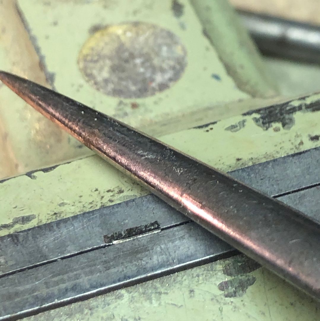
A sketch is made of the critical dimensions (from works drawings) and then a piece of brass roughed out to this size with a correct diameter hole down the middle. The rough shape was introduced using a graver by hand, rather like wood turning.
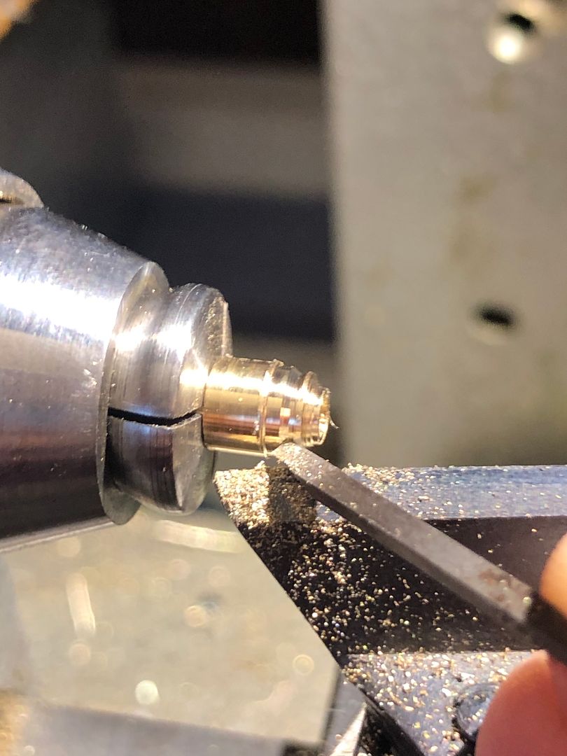
The smoother curves were made using a fine round file. Note the little finger rest upon the tool rest and the file held with a light pen grip.
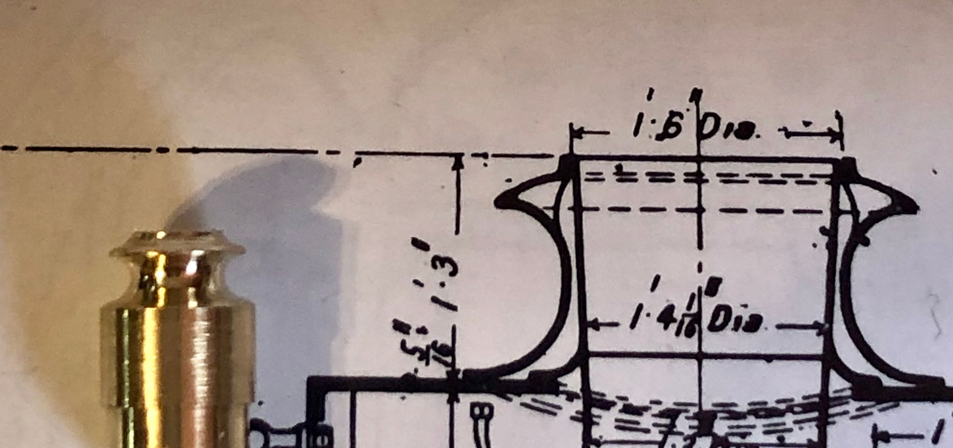
The shape was checked against the drawing and photos.
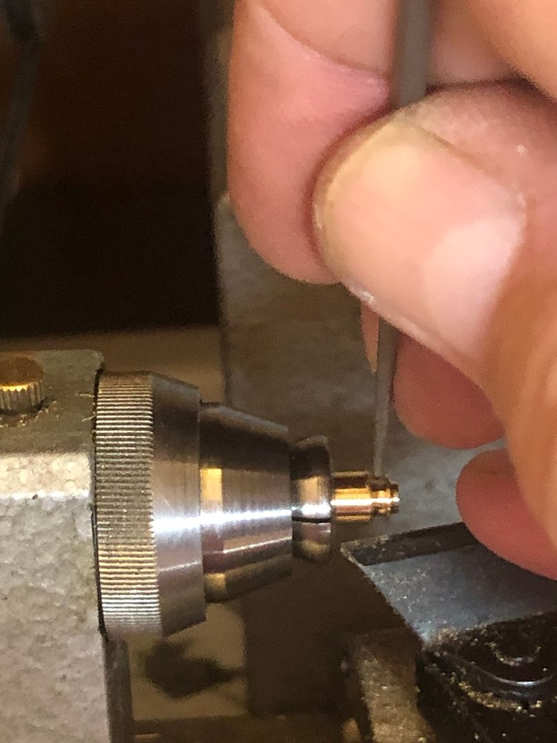
The underside of the chimney was left overlong, on parting off, so that the smoke box shape could be ground into it. When this was nearly correct the chimney was rubbed up and down some Micro Mesh abrasive cloth at the correct diameter on a rod, to develop a good seating for the fitting.
This then leaves a boiler fitting with ‘padded shoulders’.
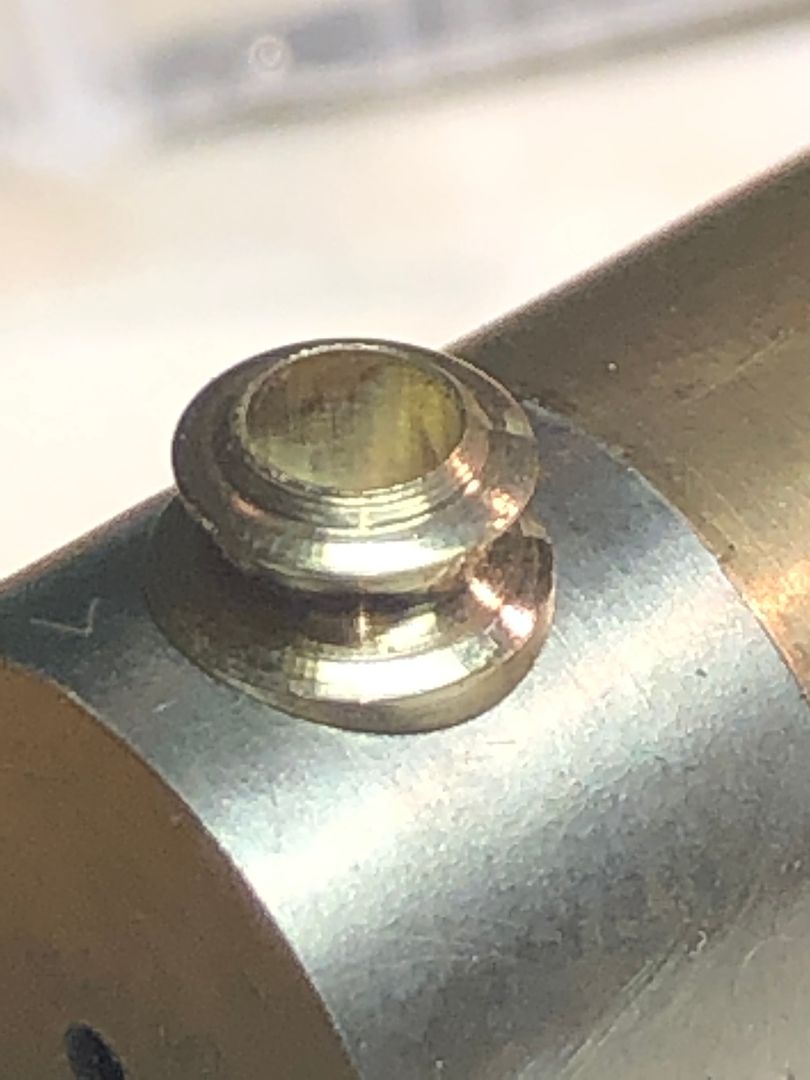
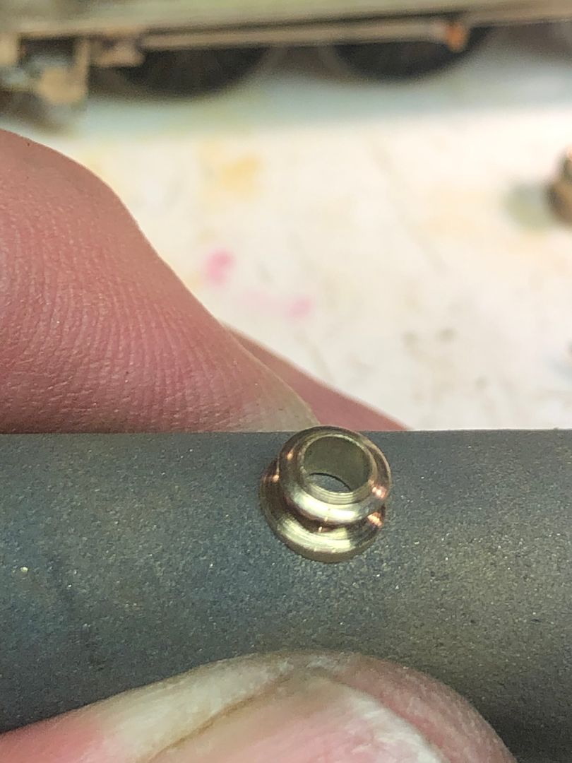
These were ground off using a pink stone in my Dremel-like hand piece and fine files / abrasives.
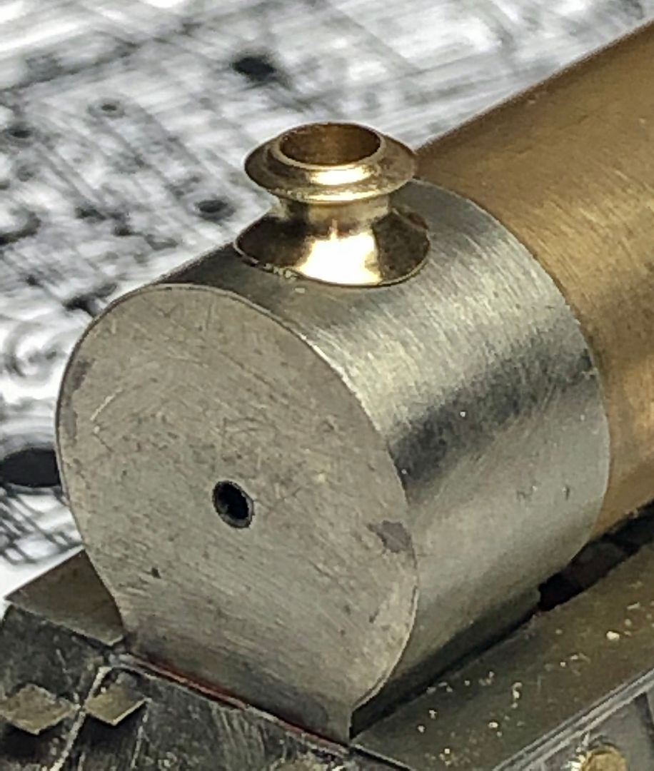
The chimney and dome are both ‘full fat’ Robinson fittings with some quite interesting curves.
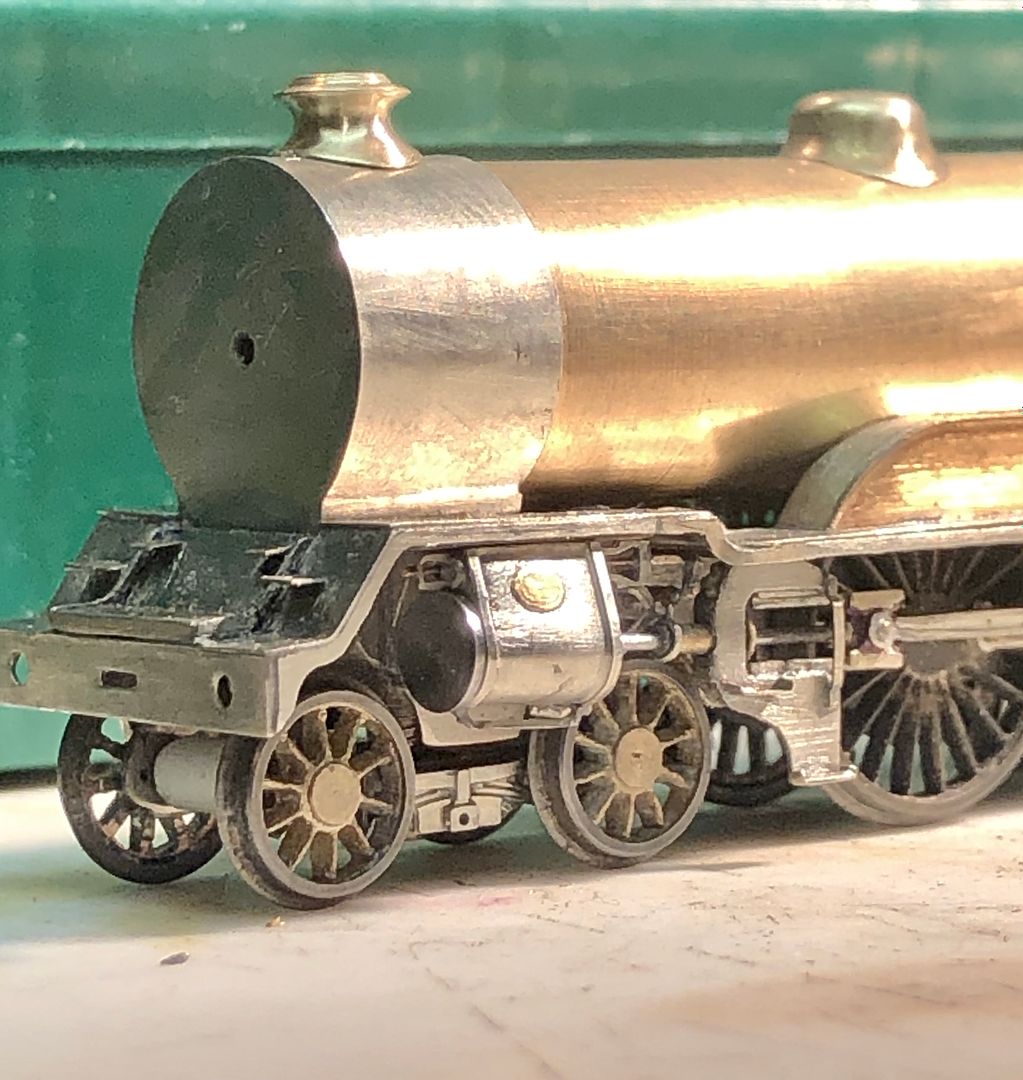
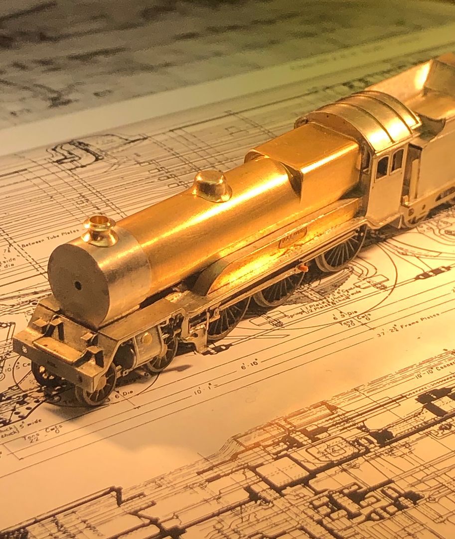
Valour is now looking much better balanced, but of course the fitting that will make a huge difference will be the smokebox door.
There are many ways of making boiler fittings, but this is the way I have preferred to make them rather than the ‘thinning the base and bashing technique’ favoured by some.
Tim
A sketch is made of the critical dimensions (from works drawings) and then a piece of brass roughed out to this size with a correct diameter hole down the middle. The rough shape was introduced using a graver by hand, rather like wood turning.

The smoother curves were made using a fine round file. Note the little finger rest upon the tool rest and the file held with a light pen grip.

The shape was checked against the drawing and photos.

The underside of the chimney was left overlong, on parting off, so that the smoke box shape could be ground into it. When this was nearly correct the chimney was rubbed up and down some Micro Mesh abrasive cloth at the correct diameter on a rod, to develop a good seating for the fitting.

This then leaves a boiler fitting with ‘padded shoulders’.

These were ground off using a pink stone in my Dremel-like hand piece and fine files / abrasives.

The chimney and dome are both ‘full fat’ Robinson fittings with some quite interesting curves.

Valour is now looking much better balanced, but of course the fitting that will make a huge difference will be the smokebox door.

There are many ways of making boiler fittings, but this is the way I have preferred to make them rather than the ‘thinning the base and bashing technique’ favoured by some.
Tim
Tim Watson
Western Thunderer
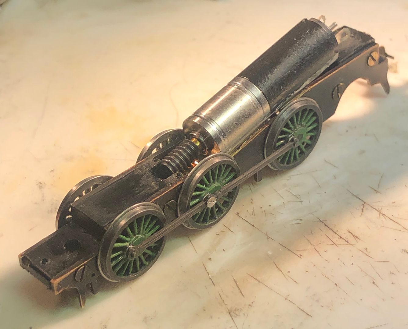
The GNR N2 failed to proceed on Copenhagen Fields at Fareham last weekend. It was made by the great Denys Brownlee and has run for 30 years, probably covering many hundred of real miles in that time.

It is very rare for me to have two engines on the go at once, but I thought this deserved a ‘12 hour chassis’ - so it jumped the queue.
On examination, I found that the 1/16” axles were worn by 0.1mm.

They were put in a step collet and have been re-profiled to 1.5 mm diameter.


On looking closer I also noted significant wear on the coupling rod pins. Denys had used remarkably thin (for him) steel for the rods and it had ‘cut in’. The new rods will be made twice as thick.
The chassis has been made with brass frames and tapped acetal spacer blocks. The frames were separated from the blocks and one sweated to two pieces of brass to act as a pattern for the replacement chassis.

The old holes were located using an equivalent size drill upside down as a plug fit in the drill press, with the frames held accurately in a vice on the X - Y table of my mill - drill. Once the location was correct, the drill was used correct way up to make the hole. The axle holes were drilled by dead reckoning, using the table to set the coupled wheelbase (the rods will be made the same way).

Once all the holes were made, the new chassis was filed up to shape using the old one as a pattern: the image shows the three pieces still sweated together.

I am fairly confident that I will be able to re-use some of Denys’ acetal spacers. It would be appropriate to keep as much of the original as possible.
Tim
It is very rare for me to have two engines on the go at once, but I thought this deserved a ‘12 hour chassis’ - so it jumped the queue.
On examination, I found that the 1/16” axles were worn by 0.1mm.
They were put in a step collet and have been re-profiled to 1.5 mm diameter.
On looking closer I also noted significant wear on the coupling rod pins. Denys had used remarkably thin (for him) steel for the rods and it had ‘cut in’. The new rods will be made twice as thick.
The chassis has been made with brass frames and tapped acetal spacer blocks. The frames were separated from the blocks and one sweated to two pieces of brass to act as a pattern for the replacement chassis.
The old holes were located using an equivalent size drill upside down as a plug fit in the drill press, with the frames held accurately in a vice on the X - Y table of my mill - drill. Once the location was correct, the drill was used correct way up to make the hole. The axle holes were drilled by dead reckoning, using the table to set the coupled wheelbase (the rods will be made the same way).
Once all the holes were made, the new chassis was filed up to shape using the old one as a pattern: the image shows the three pieces still sweated together.
I am fairly confident that I will be able to re-use some of Denys’ acetal spacers. It would be appropriate to keep as much of the original as possible.
Tim
Last edited:
Tim Watson
Western Thunderer
The coupling rods were made from two quite thick steel blanks with the holes drilled by dead reckoning in the mill / drill. These were soldered to a 1/2” x 1/6” thick steel strip, taking care to make sure that they were parallel with one edge. This was achieved by tinning the components, holding them in place with some clips and then using a miniature marking gauge to nudge them parallel with the edge. A quick flash with the blow torch and liquid flux melted the solder to attach them to the brass.

The area between the bearings was thinned down using the brass strip to hold the rods in the vice and then draw filed to make a flat surface. The raised bearing areas help to stop the fluting extending.

The flutes were made by using the same marking gauge, with the gramophone needle tip ground to a chisel shape for planing out the flute in the rods (which may have been how the originals were made).


Once this was completed, the brass was reheated with the blow torch and the two, very wide, coupling rods removed.

These were then reduced in height using drills through the rod holes to locate them in the vice. I use my fingernail to act as a stop, against which the safe edge of the file will run, when filing the areas that are difficult to see

A ‘stop’ is filed into the steel and then the material in the middle can be easily removed, finishing off with draw filing.

Final finishing includes filing in the oil caps and rounding off a few corners.

The rods are a bit smaller than Denys’ ones, but the bearing surface is greater. These rods didn’t take too long to make and steel rods are so much stronger than nickel silver.
Tim
The area between the bearings was thinned down using the brass strip to hold the rods in the vice and then draw filed to make a flat surface. The raised bearing areas help to stop the fluting extending.
The flutes were made by using the same marking gauge, with the gramophone needle tip ground to a chisel shape for planing out the flute in the rods (which may have been how the originals were made).
Once this was completed, the brass was reheated with the blow torch and the two, very wide, coupling rods removed.
These were then reduced in height using drills through the rod holes to locate them in the vice. I use my fingernail to act as a stop, against which the safe edge of the file will run, when filing the areas that are difficult to see
A ‘stop’ is filed into the steel and then the material in the middle can be easily removed, finishing off with draw filing.
Final finishing includes filing in the oil caps and rounding off a few corners.
The rods are a bit smaller than Denys’ ones, but the bearing surface is greater. These rods didn’t take too long to make and steel rods are so much stronger than nickel silver.
Tim
Last edited:
adrian
Flying Squad
Very nice

and the right colourThese rods didn’t take too long to make and steel rods are so much stronger than nickel silver.
Tim Watson
Western Thunderer
The N2 chassis was assembled, wheels quartered and after a few minor tweaks of the coupling rods it was sufficiently free turning to bond the motor gear box to the Tri-ang type cut outs in the frames with 24 hr epoxy adhesive. The worm simply rests lightly on the worm wheel whilst the adhesive is curing. The motor casing had some insulating fag paper and 24hr epoxy wrapped onto the area that would be next to the frames, well ahead of final fixing to the chassis.
It may seem sloppy practice to glue a motor in place, but there is no maintenance possible on the motor-gear box. If the worm wears then a sharp tap underneath with a screw driver will break the glue joint and the final drive gears can be replaced. We have used this approach on quite a few of the tank engines on CF. The engine hasn’t yet turned its wheels in anger with the new chassis (the adhesive is curing as I write this), but it should be alright. More to the point, we will have had a replacement chassis made within a week of failure: there will probably have been a bit more than 12hrs work to get this chassis running, but that was mainly due to the need to make some fluted coupling rods.
Tim
)")
Tim Watson
Western Thunderer
The N2 now has a working chassis. I have re-used the pick up arrangements off the trailing truck; consisting of re-curved 33SWG phosphor bronze spring to both centralise the truck and also transfer current to the chassis frames. I think these wheels are an insulated type.

The brake gear has also been re-fitted, although I probably won’t bother with the middle axle brake shoes as these are behind the steps (they do catch fluff).


The engine needs some detailing for its suburban working into KX, but it runs quite well and should be a useful stalwart again.

Some videos of it working:
Tim
The brake gear has also been re-fitted, although I probably won’t bother with the middle axle brake shoes as these are behind the steps (they do catch fluff).
The engine needs some detailing for its suburban working into KX, but it runs quite well and should be a useful stalwart again.
Some videos of it working:
Last edited:

Grahame Hedges
Western Thunderer
Wow. Thoroughly impressive.
Tim Watson
Western Thunderer
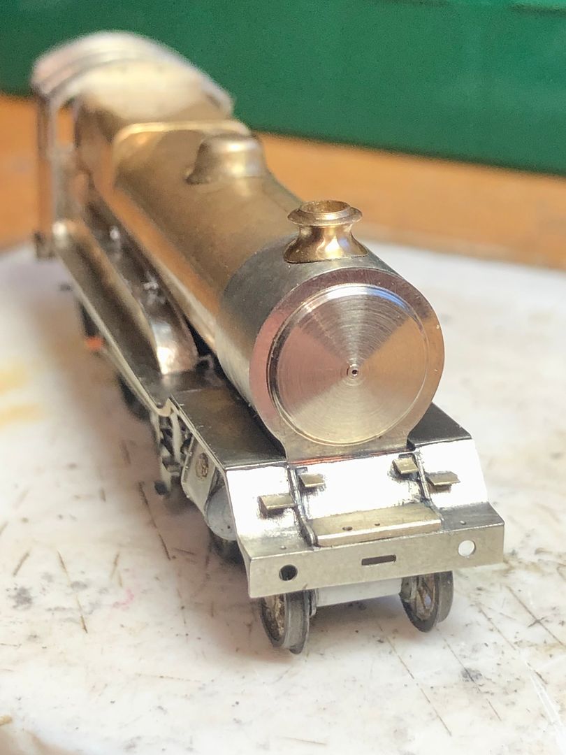
Back to working on Valour and the reversing rod and box have been fitted. Quite straightforward use of the etch for this, although I replaced the reversing linkage box with a lump of brass. It was easier to file it up from the solid rather than fiddle with the etching supplied in the kit. It will be handy to have a removable boiler for painting as the linkage is tucked in very close.

I have also turned up the smokebox door from nickel silver rod, so that the door sealing ring can be cleaned up as bright metal. It may stay removable as it locates accurately with a spigot so that the sealing ring edge is nice and sharp.
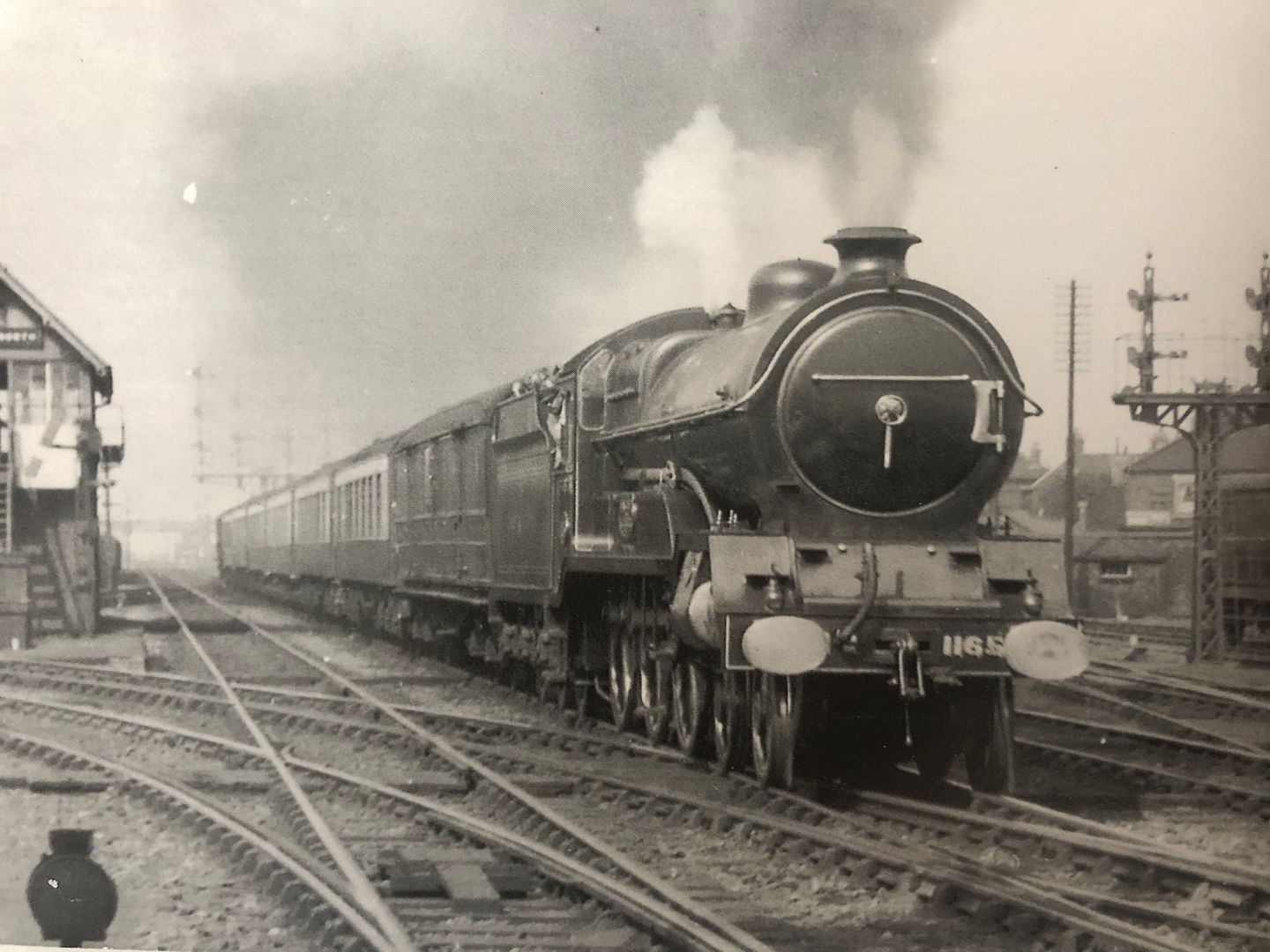
I do like this stirring photo; it also shows a wonky buffer which Valour carried for quite a while. Shouldn’t be too difficult to mimic that!
Tim

I have also turned up the smokebox door from nickel silver rod, so that the door sealing ring can be cleaned up as bright metal. It may stay removable as it locates accurately with a spigot so that the sealing ring edge is nice and sharp.

I do like this stirring photo; it also shows a wonky buffer which Valour carried for quite a while. Shouldn’t be too difficult to mimic that!

Tim
Yorkshire Dave
Western Thunderer
There are quite a lot of photos of locos and rolling stock which reveal wonky oval buffers.....")
Lyndhurstman
Western Thunderer
Stunning artistry, Tim. As always.
Cheers
Jan
Cheers
Jan
I hate steps
Tim Watson
Western Thunderer
Am I the only one that dislikes making tender & engine steps? I have made them up from the etches, but the tender ones were a bit tricky because there is a curve / angled area above the top step.
The etched top of the step was bent over and burnished to give a sharp bracket to solder to the tender body.
The tricky bit was that the change in angle occurs below that. There seems to be variations in the tenders as to how pronounced this is, but in the self trimming tender it seems quite subtle. Packing the top of the step above the vice and then bending over with a file, to exert an even pressure, produced a regular shape for all four steps.
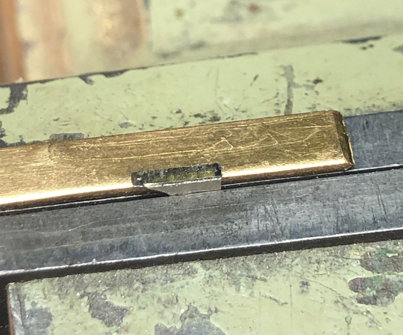
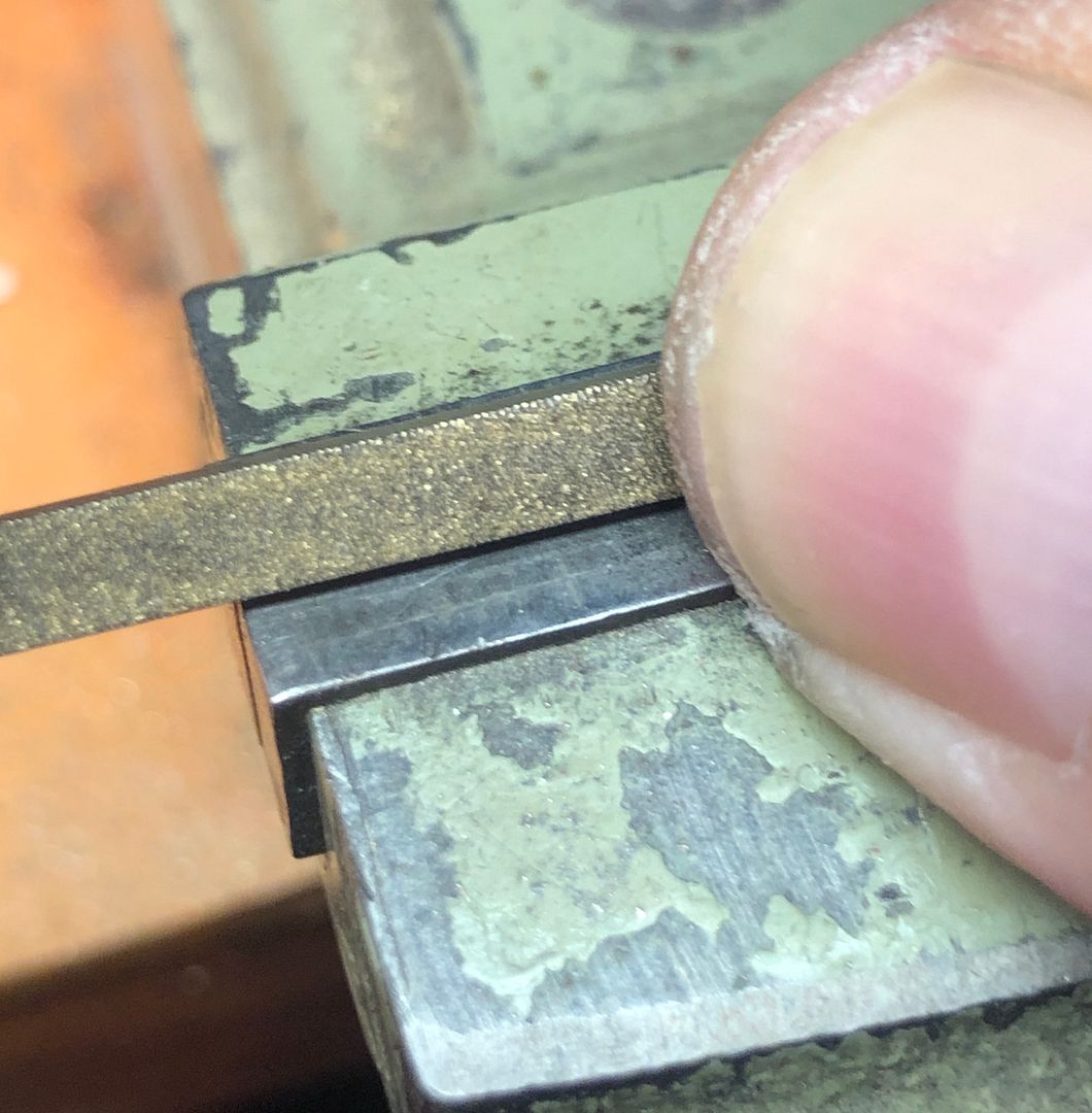
Soldering on the step bodies was straightforward. The steps themselves were etched in the kit, but at 8 thou thick are over-scale and jolly fiddly to handle. I therefore made new steps from 5 thou N/S strip. The end was bent up at 90 degrees to solder to the backing plate and then the rough size of the step weakened in the strip with a pair of side cutters.
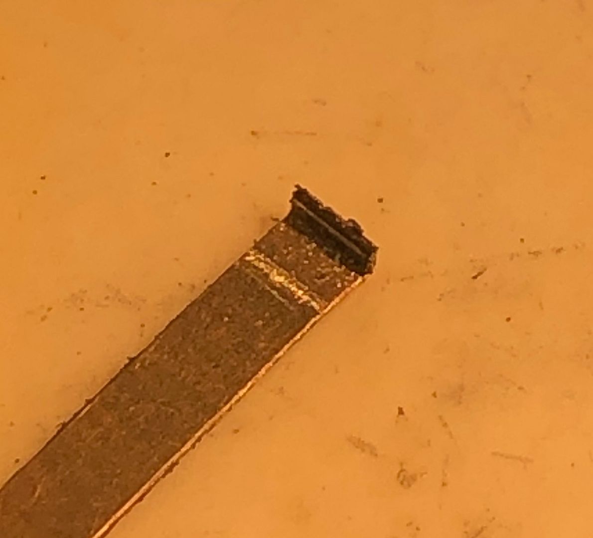
The long strip was then much easier to hold in place whilst the soldering iron was bought in to flash the tinned joint. After placement the fatigued/weakened area allows the holding piece to be snapped off the step.
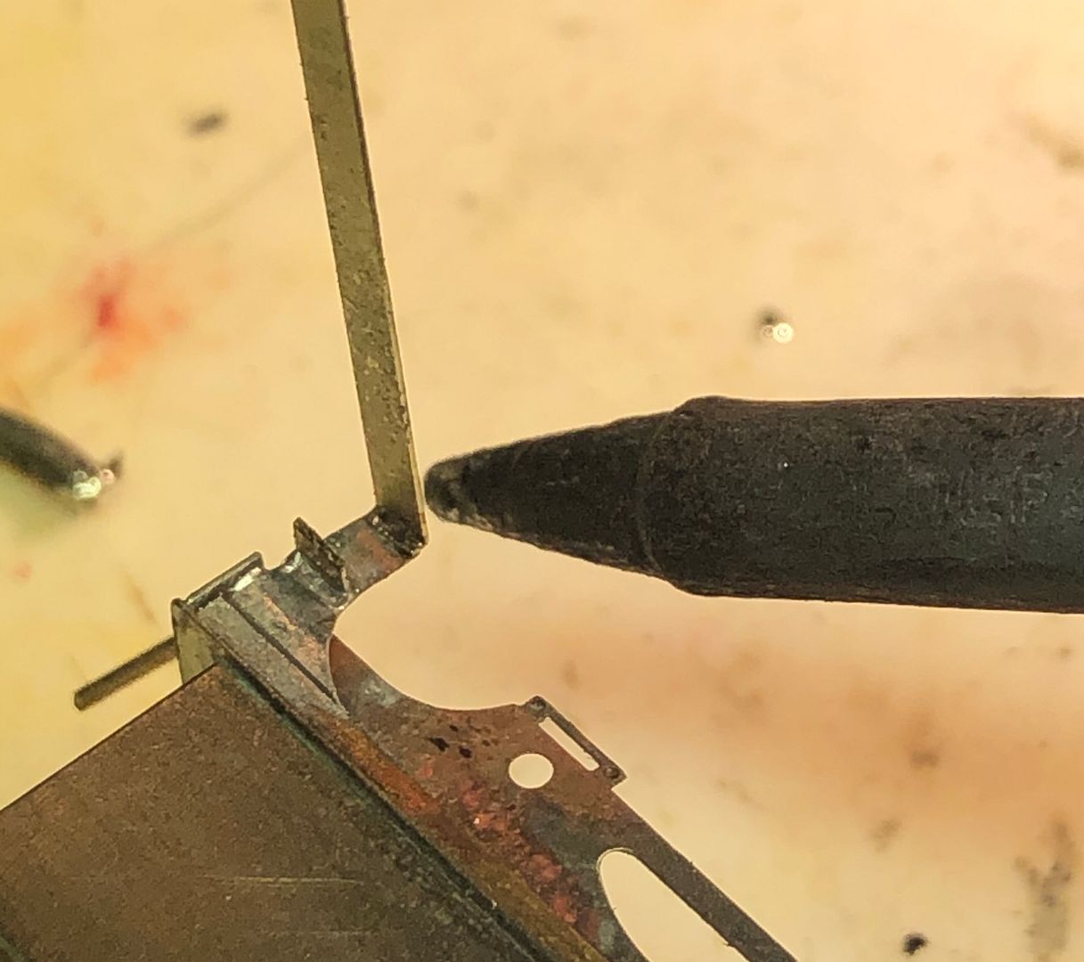
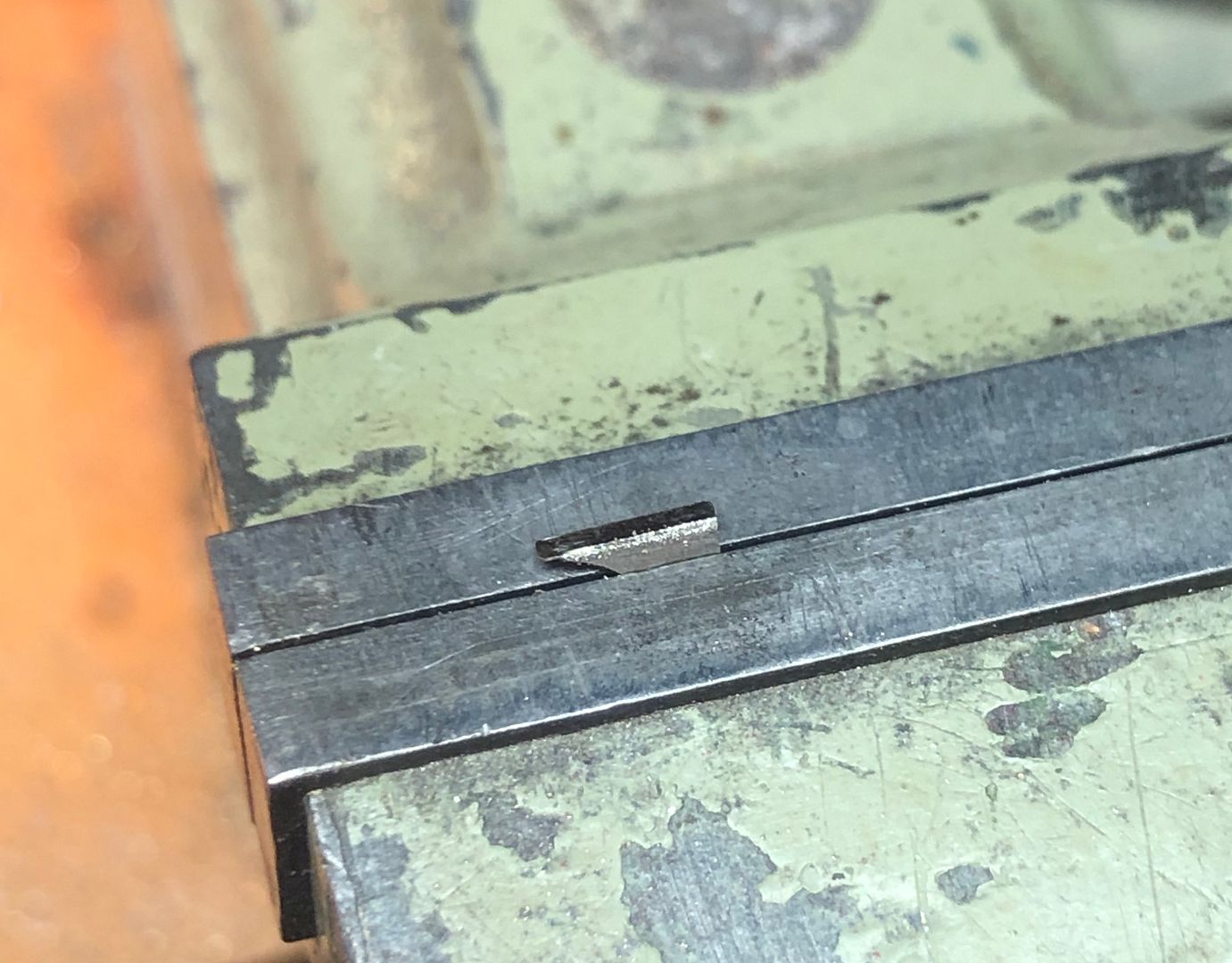
On the engine cab steps, the design is slightly different with a groove or slot to hold the steps and so the individual steps were soldered into place directly, being held by some titanium tweezers that will not take up soft solder.
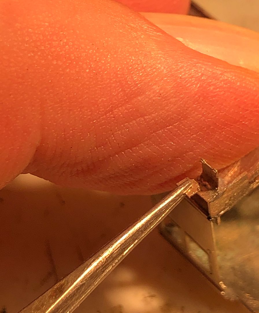
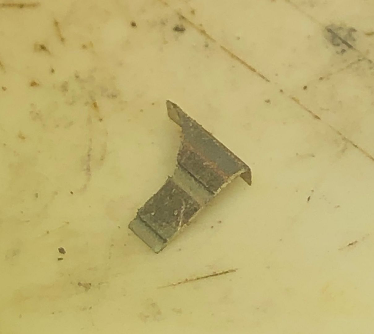
The half etched back plate for the steps produced a rather weak structure and so a bracing bracket was sweated in behind, which is also prototypical.
All OK in the end, but not my favourite job on an engine.
Tim

The etched top of the step was bent over and burnished to give a sharp bracket to solder to the tender body.
The tricky bit was that the change in angle occurs below that. There seems to be variations in the tenders as to how pronounced this is, but in the self trimming tender it seems quite subtle. Packing the top of the step above the vice and then bending over with a file, to exert an even pressure, produced a regular shape for all four steps.


Soldering on the step bodies was straightforward. The steps themselves were etched in the kit, but at 8 thou thick are over-scale and jolly fiddly to handle. I therefore made new steps from 5 thou N/S strip. The end was bent up at 90 degrees to solder to the backing plate and then the rough size of the step weakened in the strip with a pair of side cutters.

The long strip was then much easier to hold in place whilst the soldering iron was bought in to flash the tinned joint. After placement the fatigued/weakened area allows the holding piece to be snapped off the step.

On the engine cab steps, the design is slightly different with a groove or slot to hold the steps and so the individual steps were soldered into place directly, being held by some titanium tweezers that will not take up soft solder.

The half etched back plate for the steps produced a rather weak structure and so a bracing bracket was sweated in behind, which is also prototypical.

All OK in the end, but not my favourite job on an engine.

Tim
Tries hard, could do better.
Tim Watson
Western Thunderer
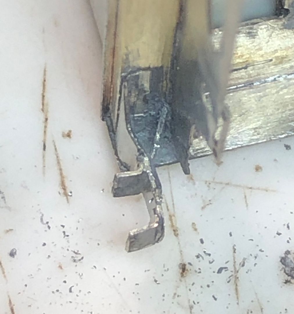
I couldn’t quite see what was wrong with the steps but they didn’t sit right. Tony Gee fortunately put me wise to the problem. The middle step should be upside down, with the support bracket underneath, not above. That way it sits in next to the angled piece rather better. Thirty minutes work to make and fit some new steps (I’ve got my eye in on this step making lark).
The steps are a little short of the buffer beam at the back because there is no side upstand.
Tim


The steps are a little short of the buffer beam at the back because there is no side upstand.
Tim
Tim Watson
Western Thunderer
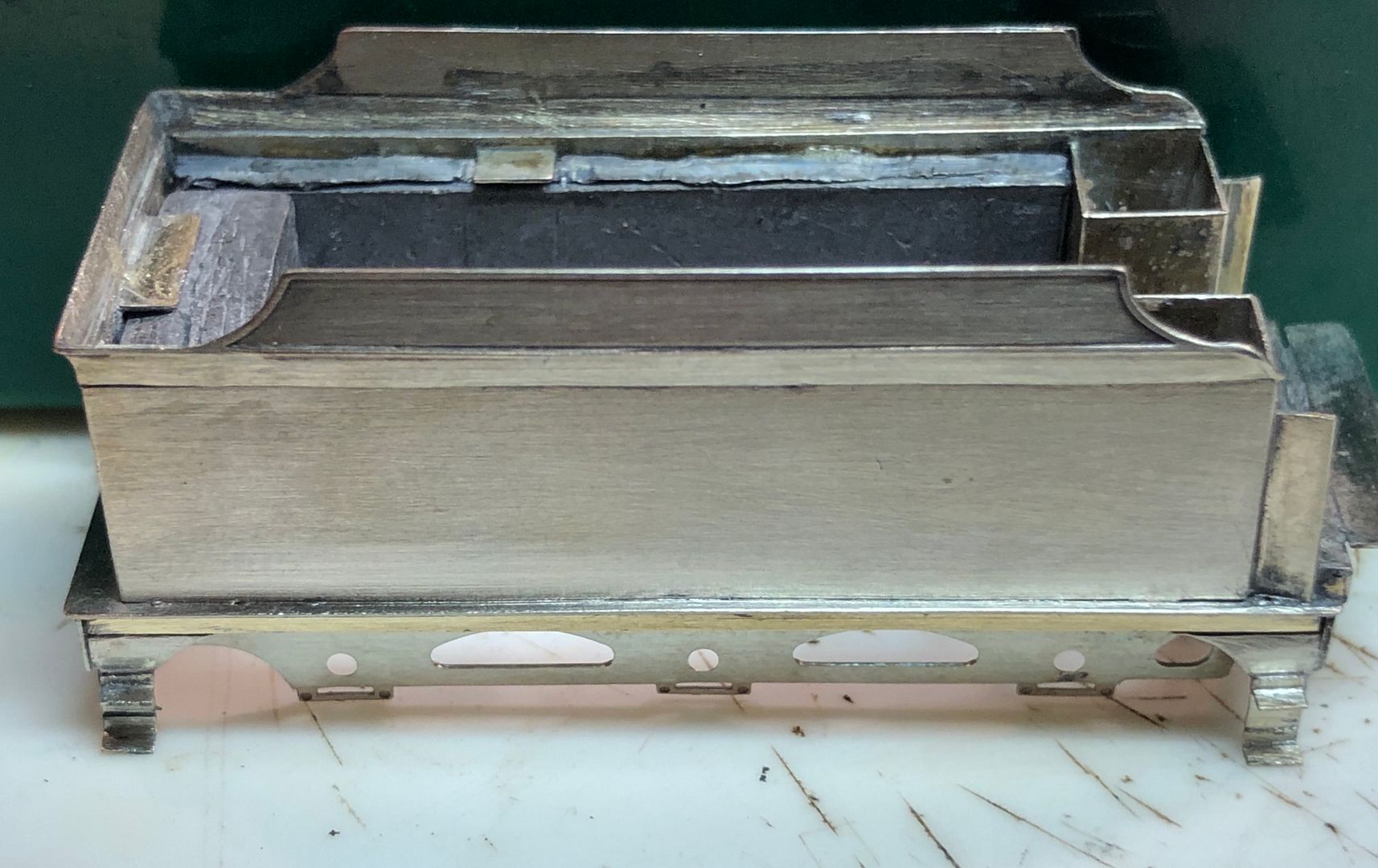
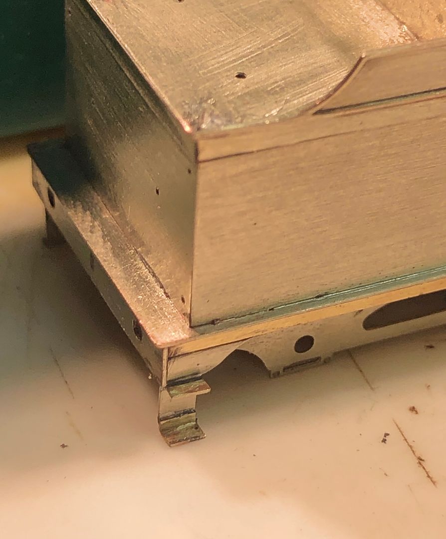
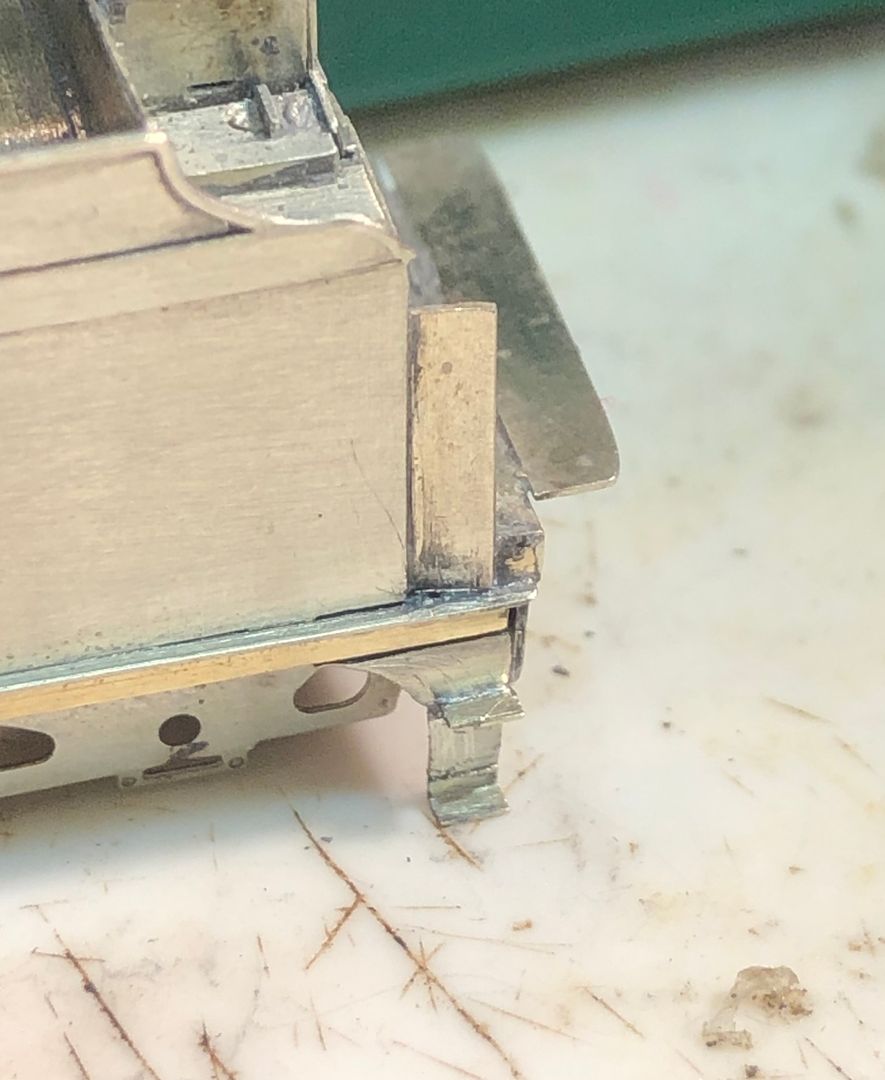
I was looking forward to making the tender filler and water scoop gear boxes for Valour and they didn’t take too long to put together. A few hacks into a lump of brass and some filing produced the quite complicated shape of the boxes and the rounded filler.
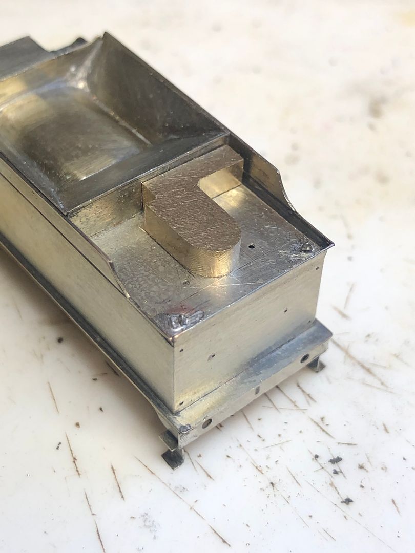
The lids were made by sweating the brass to some 5 thou N/S sheet and then filing this just about back to the brass, leaving a lip behind.
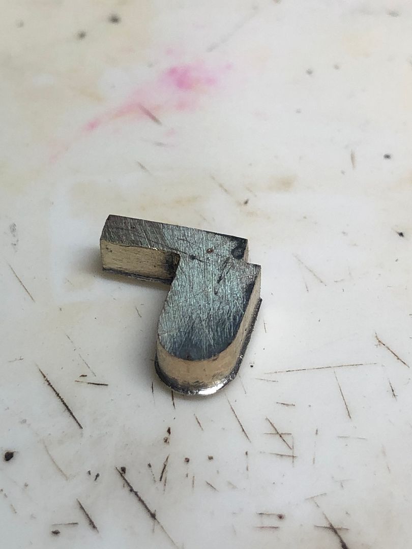
The hinges and joints were made by scribing the top with a scalpel. The handles were made by drilling a 0.3mm hole, soldering a short length of brass into it and then squeezing the round brass in the vice to flatten it. The shape of the handle was then filed into the remaining material.
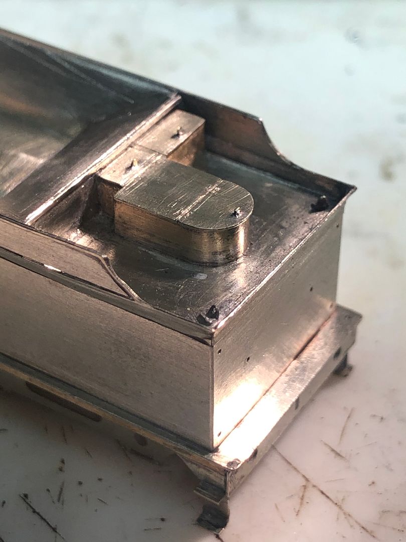
It all begins to make the tender look more businesslike.
Tim
Last edited:
P A D
Western Thunderer
Hi Tim,
Very nice. I see you have made the same set up for the water filler as it is on Butler Hendersons tender, which I assume was standard for the Robinson tenders. I followed the set up in the Gladiator instructions, but with hindsight, it sould have been easy to cut the base casting and top and stagger it. David Hill mentioned to me that he thought the instructions may be wrong after seeing the pictures you posted, so I'm sure it will be noted for an amendment.
I note also that you folded in the tender step plate above the upper step and that the step mounting plate should be folded downwards. I missed that on the prototype photos and it's not mentioned in the instructions. I'm going to leave the water filler, but I'll redo the steps.
Cheers,
Peter