You are using an out of date browser. It may not display this or other websites correctly.
You should upgrade or use an alternative browser.
You should upgrade or use an alternative browser.
Baseboard construction
- Thread starter 28ten
- Start date
Phill Dyson
Western Thunderer
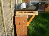
:scratch: It all sounds sturdy enough to me CME, could you post a few pics to give me a better idea ?.........but from your description it sounds similar to my methods (which have proved fine)
Phill
Phill

Phill Dyson
Western Thunderer
Those baseboards certainly look solid enough to me, what thickness's of timber are they ?. Mine are very similar....I use 2x1 tanalised uprights with the ply decking we have discussed before with no signs of warping or rot . The main difference with mine is I have mounted them on tanalised fence posts which go into 'Met-posts' into the ground.
Phill :wave:
Phill :wave:
Dog Star
Western Thunderer
This is a perennial topic and one which probably has no correct or incorrect method in the madness. For what it is worth, here is how I am building the baseboard tops for a S7 interpretation of the line between Lydney and Tufts Junction.... just do not ask why the model includes Mierystock Bridge. I say "tops" because none of the baseboards have any legs or other visible means of support - all of the "tops" rest on a substructure which is erected first so that there is none of the traditional fun to be had from trying to get legs into sockets or from collapsing boards when the leg braces come adrift.
Each baseboard is made from 4' x 2' sheets of 9mm MDF, with sides and ends from 3" strips of 6mm MDF. There are internal diagonals in the form of two "X"s and each part of those diagonals is made from 2.5" strips of 6mm MDF. All joints between top / sides / ends / diagonals are made with Evostick Impact adhesive to minimise the possibility of warping from the use of water-based PVA. There are 20mm x 20mm triangular fillets to re-inforce each joint between the diagonals and the side / end members with 15mm square PSE to re-inforce each joint between the top and the side / end members. There are pattern makers dowels to align board ends hence there are 2" x 1" PSE blocks behind the end boards at appropriate locations.
After assembly each board is given one coat of MDF primer, one of undercoat and two of oil-based gloss white paint.
Now a question... given that the top sheet of MDF is supported by verticals such that the top area is divided into eight identical triangles, what is a reasonable maximum length for unsupported 9mm MDF? (for the record, the sides of each triangle are 60cms., 42cms. and 42 cms.)
regards, Graham Beare
Jordan
Mid-Western Thunderer
Okay, Graham, I won't...Dog Star said:...here is how I am building the baseboard tops for a S7 interpretation of the line between Lydney and Tufts Junction.... just do not ask why the model includes Mierystock Bridge. ...
 but as you are modelling part of my favourite-ist UK Railway line, I'd love to see/hear more about your project, in 'Layouts' section, perhaps...

Dog Star
Western Thunderer
Jordan said:Okay, Graham, I won't...
I will put something on "Layouts" as and when I can get some photographs of the current state of play.... the model is stacked in the garage at this time whilst we build some more baseboards to extend the fun. At the moment we have a fiddle yard plus a 15' scenic section for the station (which has a low-level platform and a high-level platform). The next three baseboards are to extend the scenic section by 12' to provide for the colliery at a low-level and our interpretation of some exchange sidings at a high-level. Exchange sidings? well, just look at the track plans of Tufts Jcn. (see "Severn & Wye" by Ian Pope) and one can imagine those loops as a set of exchange sidings...... a fiddle yard in the middle of nowhere!
If you ask I may even include some photos of the sub-structure which is set up before we get the baseboard tops out of the car. Made of MDF with joints from piano hinge, so flat packs and yet stands with strength (ideas copied from Simon Thompson's model "The Field').
regards, Graham Beare
Dog Star
Western Thunderer
Now that the current work on building more baseboard tops is approaching completion I can sit and cogitate on the one problem for which an answer eludes me at this time. No matter how carefully I prepare the top / sides / ends / diagonals the baseboards often have a slight curve from end-to-end and side-to-side, in effect the top surface has a slight rise of around 2mm towards the middle. I assemble each 4' x 2' board on a larger sheet of 15mm MDF which is resting on an oak table - with the 15mm MDF sheet squared / levelled up by packing prior to starting assembly. Order of construction is to glue side 1 to the top, then ends, then side 2, then diagonals - the work is done without removing the board from the table.
I think that there is a fair chance that the top sheet is not flat before I start.... however, the question of today is:-
"How do you assemble your baseboard so that the top surface is flat?"
regards, Graham
I think that there is a fair chance that the top sheet is not flat before I start.... however, the question of today is:-
"How do you assemble your baseboard so that the top surface is flat?"
regards, Graham
Dog Star
Western Thunderer
28ten said:IMHO 2mm is within tolerance, and you may find yourself just chasing numbers in trying to eliminate the 2nm variation, which is probably caused by gluing/clamping.
You might well be correct and getting any closer to "flat" becomes a life's work. I am fairly sure that there is no impact from clamping as there is no clamoing involved in the assembly (one of the advantages of using Evostik Imapct). As to the glue having an effect, I am sure that Evostik Impact is less likely to be a problem than using any of the PVA types of glue (I did assemble one baseboard with PVA and the result was a banana... that board has been relegated to the shed).
regards, Graham
S
Simon Dunkley
Guest
Upside down and with weights put in place, or screws and glue, and then weights.
My favoured construction method now uses 9mm ply ends (100mm deep), 6mm tops and sides (100mm deep), with a 9mm central "spine" 70mm deep running the length of the board, down its middle.
I start with one end screwed and glued to the top. The end fits within the sides, by the way, so there is 6mm at either side. I then add the central spine (this can be placed a buit off centre if you know where the track will be going), which is 18mm shorted than the sides, with a screw through the end piece into the end of the spine, and a few small screws (and glue) along the centre line of the board. Ths obviously involves quite a bit of turning things over, but it pulls the centre flat.
The other end is then added, again screwed and glued. After this, the board is put upside down onto a flat work surface, and the side pieces glued/screwed into place into the ends. You can add a few staples to these joins if you wish, flipping the board over briefly. At this point, I put the assembly face down back onto the work surface with a few piles of books/magazines or whatever on the underside of what will be the baseboard surface, to hold that flat, and place either another board if there is one, or the top and materials awaiting assembly if not, on top of the frames to hold things down. I then let the glue (Resin W - won't use anything else for this work, on the advice of a joiner) set hard by leaving it alone for a few hours - have usually had enough of woodwork by this time, anyway!
Next day, I can then insert 50mm deep strips of 6mm ply into the structure to provide triangulation and cross bracing, again putting weight - a bound set of magazines is enough for this - on top of these pieces, but an hour should be enough for this stage of the process. You can also add bits of 18mm square timber into the joints, if you wish: I think this is useful along the sides most of all, and you can add these to the side pieces before you add the side pieces to the tops. (This is an idea I have just had, and wish I had had before!)
I have made boards up to 4' x 3' using this method (the 3' wide board had two central spines, but those up to 2'6" only had one) and it is surprising how few diagonal pieces are required underneath - three or four each side of the spine are enough. The resultant boards are strong, fairly light and resitant to twisting. Barry Norman tested one by standing it on end, with his feet on the end piece, and trying to twist it. There was a small amount of movement, but a lot less than with his beam and spacer ideas. He did mutter something along the lines of, "Maybe I should re-visit ply boards".
Trevor Nunn simply used 4mm ply throughout, using weights whilst glue joints set, with the boards built unpside down on a large table: see MRJ 86 for a good shot of the general idea. These boards have remained flat and stood up to the rigours of over 15 years on the exhibition circuit, and being stored in a garage between shows.
I once made the mistake of not thinking this through, and whilst I put the framing on, etc, I forgot to turn the tops over, so ended up with a concave dip which was much hard to correct than a convex one - the boards went to the tip in the end, but not until I had cut and laid about 1,500 sleepers. (Only noticed when I came to add the rails.)
Sorry, a typically long post from me (someone once claimed I held the record for length of post on RMWeb!) but I hope it helps.
I am currently without layout, so cannot provide photos.
Dog Star
Western Thunderer
Thank you Simon for your reply which has given me some food for thought.
However, there is a little snag in the middle of the post.... I quote "the board is put upside down onto a flat work surface".... just what does one do if there is no flat surface on which to place the board? I guess that my earlier post could have posed the question:-
"What do you use for a flat surface upon which to assemble a baseboard?"
Any suggestions?
regards, Graham
G
Graham Powell
Guest
HI, I'm from the Forest and had an Uncle who's father was signal man at Tufts Junction. I used to play as a kid on the site of the old Cinderford station and Drybrook
Road. My favourite bit is Serridge Junction. A railway junction surrounded by trees and no station. If you let me have your email address I can send you a very interesting picture of Tufts which even Ian Pope hadn't seen. The broad guage layout I built called Gatcombe was based on many pick nics we had on the banks of the Severn on the other side of Severn Bridge station. Ian's father Alex was building a 5 inch S and W engine. Unlikely to be finished now but the cylinders were cast from metal obtained from Lydbrook viaduct. My mum still lives in Cinderford but that was on the Churchway branch which was GWR . Never see models of Cinderford yet it was a 100 percent GWR branch line. My dad used to have a depot in the station yard and I was often sent over to the foreman to get the engine over to do some shunting. I have a model of 7741 one of my favourites which ended up on London Transport. Great days... Looking forward to seeing the layout.
rgds
Graham Powell
S
Simon Dunkley
Guest
Hi Graham,
I am lucky in that many years ago a friend gave me an "off cut" of 3/4" blockboard, to which I have affixed folding legs, and I can use that. If you leave near Oakham you are welcome to borrow it!
Trevor Nunn simply put a protective cover over a dining table and used that. If you could get away with trying something similar, you only need to do it over a couple of nights, as once you have the first board, you can use this as the base for making the others.
Alternatively, buy an 8' length of 2" square, or 3" x 2", PSE timber which is straight. Cut in half.
Buy some chipboard flooring panels, join a few together and screw to the timber. Support the timber on a couple of trestles or even lay on the garage floor.
Build you boards on this, and then take the "bench" apart. The floorboards can go up into the loft to create extra storage space, which justifies buying them on the household budget, and the timbers can surely find a use for something, like making a work bench frame (add an off-cut of kitchen surface board and you are there) for household jobs, and fix it up at one end of the garage.
This way, your hobby expenditure helps the household...")
I am lucky in that many years ago a friend gave me an "off cut" of 3/4" blockboard, to which I have affixed folding legs, and I can use that. If you leave near Oakham you are welcome to borrow it!
Trevor Nunn simply put a protective cover over a dining table and used that. If you could get away with trying something similar, you only need to do it over a couple of nights, as once you have the first board, you can use this as the base for making the others.
Alternatively, buy an 8' length of 2" square, or 3" x 2", PSE timber which is straight. Cut in half.
Buy some chipboard flooring panels, join a few together and screw to the timber. Support the timber on a couple of trestles or even lay on the garage floor.
Build you boards on this, and then take the "bench" apart. The floorboards can go up into the loft to create extra storage space, which justifies buying them on the household budget, and the timbers can surely find a use for something, like making a work bench frame (add an off-cut of kitchen surface board and you are there) for household jobs, and fix it up at one end of the garage.
This way, your hobby expenditure helps the household...
I used to be in the business of supplying model making tools and materials, I had cause to visit a company called Sandpiper models who informed me that they were about to cease trading. And everything was up for sale. Not being interested in most of the products I did spy a large quantity of plywood strips approx 4mm x75mm in a variety of lengths which looked suitable for packing materials. After about a hernia and a half of lifting the Montego estate was sagging at the knees. Unloading the ply I realised that everything was slotted at regular intervals with half joints that when crossed gave a precise right angle . The whole thing was a baseboard construction system.
Now at this point you are thinking exactly what I thought. A phone call to the seller revealed that the whole system was put together with a hot glue gun. What!!! The whole system was complete the plain end sections were punched with 40 mm holes the joiners were postal tube caps, these have serrations that gave a very snug fit. Still not impressed I decided to assemble a couple of units using some spare 5mm ply placed the lattice ply and a few sticks of glue latter
I had two 4 x 2 ft base boards . I was so impressed that I demonstrated it to some GOG members carried out some twisting and standing on tests and were suitably impressed.
Base board construction is “personal” and dependant on one’s facilities. I think that many think the heavier the better forgetting that mass can induce stress especially where screws are involved.access to a table saw and gang cutting the crossmembers plus a decent grade of ply and a similar system may suffice
The hobby has got into a line of thought that base board = timber products.
Perhaps it’s time to get a welder and box section aluminium!!!!!!!!!!!!!
76043
Western Thunderer
I used 30mm blue foam on my layout as the trackbase, not had any problems, but still had a wooden frame around it. Looking at bathroom tiling board next time, is foam sandwiched between layers of resin matting. I have a board waiting to be trialled.
 www.myqboard.com
Tony
Product overview - Qboard construction board system
All the Qboard products for easy DIY bathroom renovations: strong and flexible construction boards, shower boards, angle elements and lots more.
Tony
Pencarrow
Western Thunderer
There was a chap on RMweb a few years back that made all his boards for a very large layout out of aluminium. Seemed to take an extraordinary amount of effort and tools and money. Not sure if he ever completed the project but there did seem to be issues with the use of aluminium.
Ignore fat finger syndrome…….I used to be in the business of supplying model making tools and materials, I had cause to visit a company called Sandpiper models who informed me that they were about to cease trading. And everything was up for sale. Not being interested in most of the products I did spy a large quantity of plywood strips approx 4mm x75mm in a variety of lengths which looked suitable for packing materials. After about a hernia and a half of lifting the Montego estate was sagging at the knees. Unloading the ply I realised that everything was slotted at regular intervals with half joints that when crossed gave a precise right angle . The whole thing was a baseboard construction system.
Now at this point you are thinking exactly what I thought. A phone call to the seller revealed that the whole system was put together with a hot glue gun. What!!! The whole system was complete the plain end sections were punched with 40 mm holes the joiners were postal tube caps, these have serrations that gave a very snug fit. Still not impressed I decided to assemble a couple of units using some spare 5mm ply placed the lattice ply and a few sticks of glue latter
I had two 4 x 2 ft base boards . I was so impressed that I demonstrated it to some GOG members carried out some twisting and standing on tests and were suitably impressed.
Base board construction is “personal” and dependant on one’s facilities. I think that many think the heavier the better forgetting that mass can induce stress especially where screws are involved.access to a table saw and gang cutting the crossmembers plus a decent grade of ply and a similar system may suffice
The hobby has got into a line of thought that base board = timber products.
Perhaps it’s time to get a welder and box section aluminium!!!!!!!!!!!!!
If you are in a hurry and the wiring is simple, flush interior doors ( egg boxes between ply type) gives you a reasonable start, especially if a refurb and cost free….
Big j
Jordan
Mid-Western Thunderer
Quite possibly. I think 'exhibition layout' "thinking" influences 'layouts that never leave home' rather too much at times!!The hobby has got into a line of thought that base board = timber products.
Perhaps it’s time to get a welder and box section aluminium!!!!!!!!!!!!!
For instance, hidden sidings. Probably essential on an exhibition layout, but at home, in front of an audience of one? Possibly not - my main layout, a "roundy" in my loft, is all scenic. It takes the same imagination to believe a train has come from miles away, when in reality it's come from the other side of the layout, regardless of if the point of origin is hidden or not!!
The boards for my layout are slightly different to the 'norm', too. They are Knauf Spaceboard extruded styrofoam, glued& screwed to wooden 'T' girders, screwed to the purlins, with hardboard strips as a fascia. I had to add more T girders when I changed from HO to O Scale.
It does amuse me that boards are built strong enough to stand on, when they only have to support the weight of model trains.....


