Brushs Laser Cutting and 3d Printing workbench

Osgood

Western Thunderer
Early plates were quite large castings but soon became sectionalised enabling smaller plates to be used.

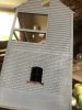
I would have thought the bridge shown below would have used three plates with joints at red lines - this makes sense when you look at the holding down bolt locations. Bolts were only used at ends of plates - not in centre where they might stress the plates (the plates sat on timber packers above the main girders, so bolts really just located plates and stopped excess vertical free play).
Pooley Plates.jpg
Also note that most plates have uniform thickness webs at ends, so there would be a double-thickness web along joint lines, similar to the outer end of the plates?

Not always though - I have an early 20T Bartlett bridge using 1 x 8ft w x 8ft plate and 1 x 8ft w x 7'11 1/2", instead of using two identical plates.
The joint is offset by 1/2" and the pattern spacing changes by 1" in centre - oh well.
 

Eastsidepilot

Western Thunderer
Phil and Tony,
I have always planned to build a rail weighbridge on Bow Creek, one of things that has had me wondering is would the loco be allowed over the weighbridge ?
Col.
 

BrushType4

Western Thunderer
Phil and Tony,
I have always planned to build a rail weighbridge on Bow Creek, one of things that has had me wondering is would the loco be allowed over the weighbridge ?
Col.
I guess it would depend on the axle spread. Is it possible the even a heavy loco would be lighter per axle than a fully loaded wagon?

Edit. Thinking about this, I guess a loco is pretty much always going to be heavier. I suppose the reality is that yards were shunted more often by horse power than loco power?
 

Osgood

Western Thunderer
Well, I have not yet found any photographic evidence of use of dockside rail weighbridges, (there were plenty of colliery single track bridges used by locos), but thinking it through:

A loaded 4 wheel 8 plank timber coal wagon would be around 19T (tare 7T, payload 12T), so a 20T bridge would have only just enough capacity.
I seem to recall seeing a pic of a 24T bridge but can't find it.

A more modern 16T steel mineral 24T (tare 8T, payload 16T) so a suitable weighbridge would be say 30T capacity.

I guess the makers of the time (are you early 1900s?) would not approve any overload so a loco would have to be within bridge capacity.
There was no lock-out of the main knife mechanism - only maybe for the head steelyard.

Certainly overload capacity was built in - Avery in the early 80s approved us upgrading an old 30T Pooley bridge that they maintained to 40T by changing the rotary mechanical head (and we later fitted an electronic loadcell to the pit arm in the late 80s).

A GER Y5 0-4-0 was 21.2 T, a Y4 was 38 T. Mmm.
 

Eastsidepilot

Western Thunderer
I guess the makers of the time (are you early 1900s?) ..............

.............A GER Y5 0-4-0 was 21.2 T, a Y4 was 38 T. Mmm.

I've based Bow Creek in '46 ish so the Y4 would be the only loco I'm using although the odd sentinel might appear, with an option for bringing early diesels in by bringing the era forward via a time warp :D.

But I'm thinking now that it might be more prototypical to just have a conventional weigbridge for road vehicles.
Col.
 

Oz7mm

Western Thunderer
Of course any self respecting Pooleys set up should have the weighing machine in the hut.

This one was 3D printed but I guess we could get them cast. Perhaps Phil could offer them as a set.

I would have extracted it from the weighbridge hut for a better picture but that nice Mr Insole has stuck it down.

John

pooleys-s.jpg
 

BrushType4

Western Thunderer
The paint shop is fully stretched at the moment and we’re busy getting bridges, signal boxes and I don’t know what completed for handover to customers at Telford.

Within my Intentio kit range I have a design your own GWR Signal Box. A customer here has specified options for a Signal Box based on Cranmore.

I just sprayed a witness coat over to make sure the build was true this afternoon.
15D375E8-BCE4-47EB-861F-6EC7FEE4FD45.jpeg 54B95A2B-AB60-4768-A6B2-2E15A5D67EDE.jpeg DA3A20ED-3F82-4A5E-AEF5-86503F39F837.jpeg F9C576CC-3CDC-40C9-9E91-335D93152CF8.jpeg BCDD6042-A801-4FF4-B3A1-2FF360CD7941.jpeg A5FB4BD7-0CB0-4B42-8785-C1A152D8DF20.jpeg
 

BrushType4

Western Thunderer
This box is finished as far as I’m going to be doing. It’s off to the customer now for final finishing and painting. I think it will be at Warley later this year.

I built up the chimney stack and under coated in Halfords red oxide. Went on a bit thick but is easy sorted out and I’ll leave that.

The signs are lasercut too. The plastic does bend a little when cutting due to the heat but they are bendable. I’ve added scotch3M double sided tape to the box sign to make fixing as simple as peel off and press down.
D8BE013D-4464-41ED-85CC-0E648D1B4682.jpeg
 

LarryG

Western Thunderer
Things are coming along nicely with new ideas that take the strain out of fitting some details. Signalbox window frames are something I looked at etching, but my pal wont be drawing any CAD's now for some months. What is the footprint of your 'Cranmore' signal box?
 

BrushType4

Western Thunderer
Things are coming along nicely with new ideas that take the strain out of fitting some details. Signalbox window frames are something I looked at etching, but my pal wont be drawing any CAD's now for some months. What is the footprint of your 'Cranmore' signal box?
It needs approx 275mm x 90mm including the stairs.

The signal box windows are press fit, no glue if you don't want to. I designed them to be replaceable in case of heavy handling needing replacement.....

I've a single Cranmore Style Box Kit available but that won't hang around long, or I can make virtually any GWR box from my portfolio of modular lasercut part library. Or any box by commission :)
 

BrushType4

Western Thunderer
A bit more progress on the signal box today.

DD0071F3-D611-4B95-A1C2-2A1C1278457A.jpeg 0FF7562F-5F8C-43B1-ADD0-1FAAC69B4DA8.jpeg 00F99484-D3D9-42F0-8175-F1C0765CFCFC.jpeg ABE5AA0A-BBBF-4361-88F9-7E789F647702.jpeg

The brick corner isn’t perfect but I’ll sort that by running 400 wet and dry sand paper over. The mortar won’t fade and once paint is applied it will be ok. Because the thickness of the MDF is variable, I make the teeth a little longer. Sanding back is easier than trying to fill back up which I’ve found is time consuming and difficult to get right.

The snagging list is getting longer so this actual box will be scrapped and fresh parts cut out. I’ll continue with it here though so I can make sure the rest of the parts fit and look right.
 

BrushType4

Western Thunderer
Intentio towers had the pleasure of @Peter Insole today. While examining the Lancashire and Yorkshire Signal Box, Pete gave some constructive advice regarding the thickness of the window frames. Reluctant agreement is that he is right, but luckily, its a quick fix to the drawing and the original box already had been assigned to the bin due to snags.

It also gave Pete and I, a chance to review some other areas I wasn't sure about. Namely how the boards at the rear would have fitted. I had an inkling that the fire place would have meant that the central section of the top rear would have been brick. No actual evidence was found, but Pete found a picture of a refurbish box that very clearly showed a join were we expected a brick fireplace. The refurbishment had removed the fireplace and no doubt installed more modern heating.

So CAD changed and updated. New parts ready to cut out. A new build will take place over the weekend and kits produced.

I had some full size lasercut 'Western' letters waiting for post and these were spied by Pete and he told me of the time back in 1975, he rode behind Western Firebrand the day it died. After Pete extracted 16 letters off me for said name, I expect soon to see a Pete Insole Western Nameplate appearing on his thread!

At the other end of the Intentio empire, updated CAD for our latest range of engine sheds appeared. I'm very excited about this, as this model is scalable to the 2 and 3 road types seen across BR including Kings Cross Top Shed that I have a personal interest in.

While the kit will be supplied from MDF and acrylic, this has also been designed to build from 100% exterior grade acrylic for the Garden Railway Modellers among us. We are also thinking about how our other kits can be revised to exterior proof, particularly the signal boxes.

67884084_1122006061330388_790901790718558208_n.jpg 67871112_1122006091330385_167049742205845504_n.jpg 69372169_1122006104663717_9054035370592698368_n.jpg
 
Last edited:
Top