Building an Ace Kits "K"

Peter Cross

Western Thunderer
So pleased to see this come almost to the end. You've made a cracking job. I have always liked the K class after building the K's one many years ago.
I am at this moment building yet another Ace kit. An E2 into a certain little blue engine for my 2 year old. William has done his best to make this one hard too.
 

oldravendale

Western Thunderer
Here's the next challenge.

Turn this:

IMG_20180308_170634976 - Copy.jpg

in to a back head.......

So I bought the lost wax back head set for the LBSCR Atlantic from Laurie Griffen. Unfortunately nobody seems to make the back head moulding for a "K", so it was either take Simon T up on his offer to create a pattern for the back head in white metal, at a considerable lead time, or create a multi layer brass back head filed to shape or...... use what was provided. Having made a number of Belpaire fireboxes as designed with fold up parts in kits I decided that this would not be beyond me utilising the Simon T "blobbing" technique with high temp solder.

This is what I ended up with, after fitting the LG firehole, a few wash out plugs and drilling some more holes for the other castings.

IMG_20180619_165612545 - Copy.jpg IMG_20180619_165629728 - Copy.jpg

Here's the "dry run" using the best compromise parts I can cobble together. Most of the cast pipework will be removed and replaced with copper bent in to appropriate locations. There will also be some fine wire to provide the feeds to the gauges on the cab sides and front. The strange object on the right of the photo is the scratch built driver's seat which will be vertical on the cab side.

IMG_20180619_165237997_BURST000_COVER_TOP - Copy.jpg

I think I'll paint the back head before fixing the components.

B
 

Scanlon

Western Thunderer
Brian,
On the bottom photo I see you have put backhead clacks on. These are incorrect as you have built the loco with clacks on the boiler side. You will need to source steam valves, i.e. single pipe only not the twin ones currently shown. The photo of the K in Ashford works "British Railways Illustrated Vol.21 page 78" might be of help to you. The photo also shows the twin feed lubricator located below the fireman's window although that might be difficult to source. I think Hobbyhorse used to do one but can't be sure.
Roger
 

oldravendale

Western Thunderer
Thanks Roger. Very helpful. I think Steph may be along in a minute with some similar and additional comments. Yes, I have that photo from "BRILL" but it's a bit too gloomy for me to determine what is what. Fortunately none of the parts are fitted yet and I'm very pleased that I put the photo up before fixing everything in place. It was rather one of those "make it up as I go along" bodges, but this one has not worked out.

There may be a twin feed lubricator in the pack I bought from Laurie Griffen. Certainly I've not placed all the cab side accoutrements and dials in place yet. These will wait until after painting anyway.

Back to the drawing board (and any other helpful comments will be appreciated).

B
 

Steph Dale

Western Thunderer
A quick check of emails and responses here - I shall, for once, acquiesce to my father's wishes... :rolleyes:

What I emailed to himself yesterday was:

"""
The K seems to be rather over-endowed with injectors. You've got four on the backhead alone. Worth checking where the brake ejector and combination brake valve goes too...

Two of the injectors you've put on the backhead should be (I think) steam valves for the injectors, which are Ashford type under the cab and feed the boiler side clacks. You'll then need one more steam valve for the Westinghouse pump. There may be a further valve on the backhead for steam heat and don't forget to take the blower handle back through the left-hand boiler handrail to match the valve on the smokebox side. I have to confess that I don't know where the Westinghouse pump regulator is on your loco - it could be on top of the pump itself or maybe inside the cab somewhere, on the same side as the pump.

You almost certainly need a BR-era cab/backhead photo. I'm guessing you've been using a LBSCR/early SR one?

I'm very impressed with the way you've formed the backhead from that **** and **** piece of **** brass though; that's very impressive indeed. :)
"""

With luck I'll get away with that... :))

Steph
 

oldravendale

Western Thunderer
Thanks Steph.

I'm certainly happy with where I am so far, but not, now, with the back head! I reckon it's helpful to have this in the public domain as there may be more assistance out there which will help me to determine t'other from which.

My reply is:
Thanks for this help, Steph.
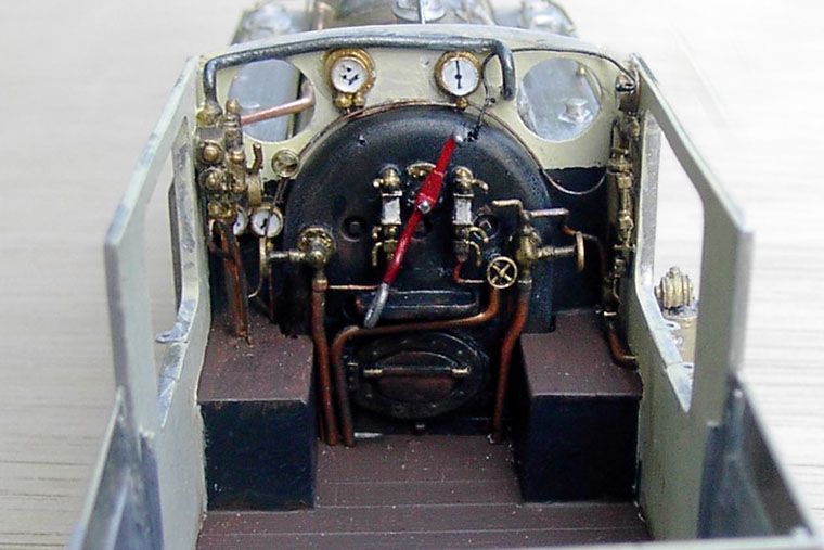
The problem for me is that I don't know what is what! I sort of made it up as I went along. I don't have a good photo of the back head except for an LBSR one, and those I do have are a bit gloomy. I have a drawing of a B4 back head, is it? The one for the Atlantic isn't a lot of help. I think what I may do is wait until I see you to complete this, but I'm glad I put the photo up so I can be put right! Roger Scanlon has sent me a similar PM.

As ever help will be gratefully received. Initially, perhaps, so that I can identify the injectors and also the backhead clacks. Once I know what these are I can at least start to put that aspect right! I'll then drain the rest of the knowledge from the assembled throng.

Would have been helpful to have a drawing of a typical backhead included in the instructions, though, would it not?

B
 

Martin Shaw

Western Thunderer
Brian
Talking of over endowment your gauge glasses have rather too many shut off handles, in fact twice as many as necessary. Personally I'd keep the ones on the inside for the top and bottom of the glass and the outside ones for the drains, based on nothing more substantial than it feels right.
Regards
Martin
 

Steph Dale

Western Thunderer
@oldravendale.

First post of this thread indicates that you have a cab backhead arrangement:
Swap out the backhead mounted injectors/clacks from the drawing and replace with a couple of (probably Ashford-style) injector steam valves; the pipes from which will run down to the Ashford injectors under the cab.
The steam valve for the Weir pump diverts down to the injector on the LHS of the cab, but would otherwise be unchanged.
The SR combination brake ejector would have to go on the LHS of the backhead within reach of the driver - @Yorkshire Dave can probably advise what happened to the Westinghouse brake valve as that would have been reflected on his E4, like this:
cab01.jpg


Robert will shortly be your mother's brother.

Steph
 
Last edited:

oldravendale

Western Thunderer
Hi Martin.

Thanks for your advice re the shut off handles. Yep, I recognise that one or the other on each side will have to be trimmed, but this is just (fortunately) the dry run. Nothing added, nothing taken away except for the raw castings.

....and thanks Dave. Yep, B4X it is, and I have the drawing courtesy of an earlier post on WT. I'm having difficulty in getting the castings I have to match up with the drawing, but I'll have another go. It is, of course, just possible that the castings are not right, even though they are Brighton. And thanks Steph. I'll study your advice and see whether I can cobble up something which might bear a feint resemblance. I have the photo of Dave's E4 cab on the bench at the moment.....

Brian
 

oldravendale

Western Thunderer
Bum!!

And bum multiple times more.

Just finished spraying the loco and tender chassis satin black. Lovely.

Then the loco, broken down to boiler, footplate and cab gloss black. Lovely.

Then the tender body. BUM!! I have a run in the gloss black on one side. That means I'll have to wait a couple of weeks before I can rub it down - either that or strip the whole thing and start again. On balance I'll wait.

I've also been practising lining with my new Haff bow pen. We'll see how that comes out, but practice so far is not looking good. That may be associated with an unsteady hand (mixture of a misspent youth and old age) so I'll see what it looks like. If I don't like it I'll strip the lining off with white spirit and go for transfers. Life is just too short.

And BUM! again.

I feel better for that.

Brian
 

simond

Western Thunderer
Brian,

Can you not strip just the offending side, mask & respray?

Acetone and cotton buds.

I feel for you, I ended up there with my Castle tender...

(And gave up on the lining, and asked Warren H to do it - and he stripped and resprayed it again, which did wonders for my ego... but it looks good)

Best
Simon
 

P A D

Western Thunderer
I've also been practising lining with my new Haff bow pen.

Brian

Hi Brian,
When you say "bow pen", do you mean a drawing/ruling pen, or a spring bow pen?

A bow pen is a bow compass with a pen attachment and is completely different. I believe the term bow pen was used by some of the early pro model painters, but is not correct for the two instruments most commonly used for lining. That said, I believe that Larry Goddard started out using a bow pen for offset lining, but it is not the best tool for the job, as the only way to lock the setting would be to over tighten the head screw.
Yes, I know, I'm a bloody pedant. Rant over.
Cheers,
Peter
Drawing instruments names.jpg
 

oldravendale

Western Thunderer
I could do as you suggest, Simon, but suspect, once I start, that I'd end up stripping the entire paint job which I'd rather not do. I'm going to give it two weeks and try rubbing down at that point. If that fails, then I'll have to strip it anyway.:)

I thought of involving Warren, but am committed to doing the best I can by my own fair hand

Apologies, Peter. Haff do, indeed, call it a drawing pen.

Brian
 

Jack P

Active Member
That boiler back-head is fantastic! I'm in awe of what you've made of this - I actually joined WT to let you know how much of a good job you'd done, and now i'll re-read this thread with all of the pictures full size! I had considered starting the 4mm version but I managed to get my hands on a whitemetal kit, which means I (luckily/hopefully) won't have the same struggle you did! Definitely worth the effort though, how's the painting going?

Brian, if you do have the numbers to hand, what are the prototype length measurements of the coupling/connecting rods??
 
Last edited:
Top