7mm DJH Streamlined Coronation.

simond

Western Thunderer
Thanks Rob,

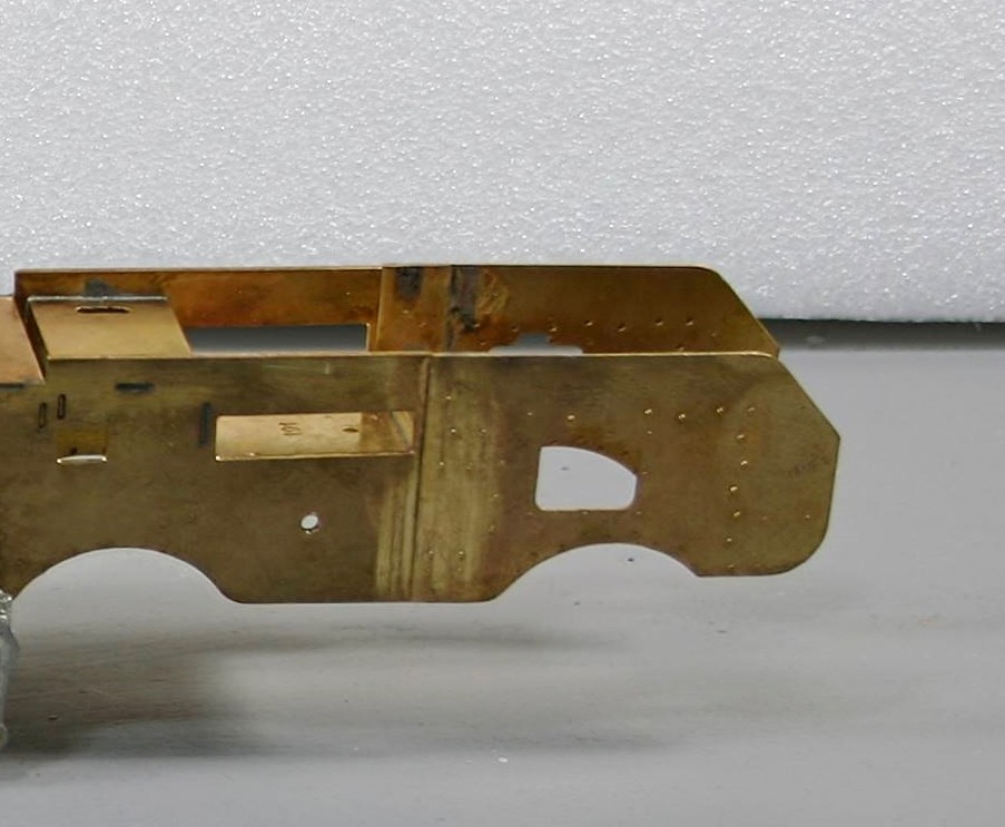
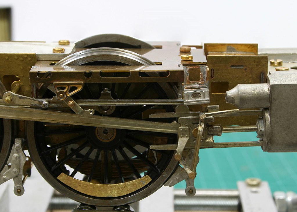
You’re probably aware of my Premier-framed build on RMW, I doubt that the double row will be visible behind the cylinders, so I’ll not lose sleep over them, similarly the ones around the weighshaft pivots are pretty well hidden by footplate and the lifting levers.

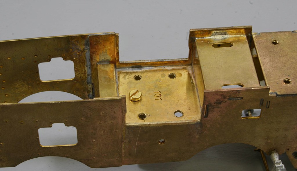
The ones where the rear frames come off the main frames are perhaps another story. In any case, visible slotted csk screws in this area are perhaps not quite de rigeur.

Thanks again
Simon
 

Rob Pulham

Western Thunderer
No problem, and yes I have been looking in at the goings on:) It's a real challenge trying not to disturb the paint job...
 

Rob Pulham

Western Thunderer
I was cracking on quite nicely with the chassis but when I got to the next phase of the instructions I found one of the castings missing.

This is the offending article, there should be one at each side.
41658275072_0dd3c826cd.jpg


After umming and ahhing as to what to do I decided it would be simpler to scratch another than to wait for the owner to source one from Tower/DJH.

Poor photo but this is it made from scrap etch and some wire filed half round.

27829826778_0b4234892c.jpg


27829161998_b7bf741259_b.jpg


40979715464_a17c426e97_b.jpg


Next saw me make up the coupling rods which all went swimmingly until I got to pinning them together at the joint. The instructions have you tapping one side 12ba to screw a cast threaded pin into. Having done the first side I quickly realised that the thread on the pin is way smaller than 12 ba Bah!! :headbanger:

The other side I tapped 14ba and I ran a 14ba die down the cast thread, I screwed it into the tapped hole and the threaded section promptly broke off in the hole :rant:
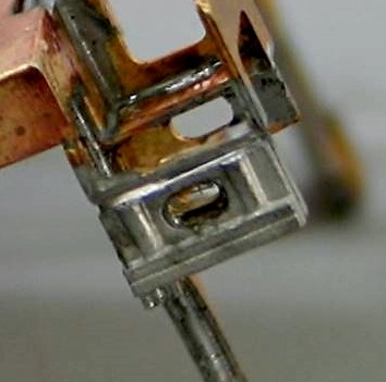
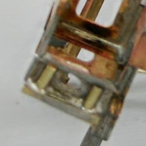
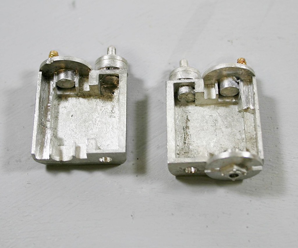
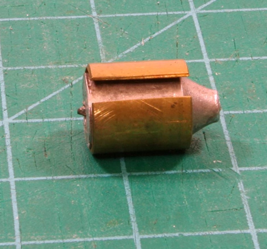
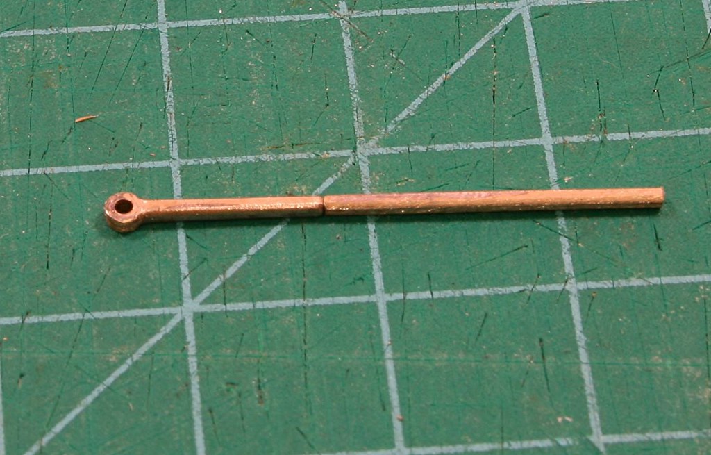
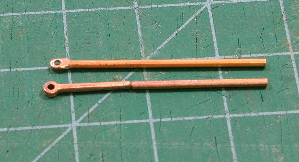
The next task was to solder the pins into the back of the hole as I would have done with a rivet of Premier Rods. Onwards and Upwards.....
 

P A D

Western Thunderer
Hi Rob,
City of Birmingham also has the lower ram missing. I think towards the end of steam they were just removed if they needed repairs.
Cheers,
Peter
 

Rob Pulham

Western Thunderer
Following on my my note on the coupling rods I managed to get a couple of photos of them now that they are soldered up.


26906815917_c696c269c8_b.jpg


And then a couple that will hopefully show how much I had to file out of the cylinder castings....

27906269118_f6bec9ebea_b.jpg


26906816367_1bcb8cf86a_b.jpg


Essentially the slots bottom left and top right were almost full of whitemetal so I used an older square file to remove the material. Now that I have the lathe with the milling attachment I suspect that I might have used a burr to mill out the material much more efficiently. Something to remember should I encounter anything similar in the future.
 

Rob Pulham

Western Thunderer
After doing battle with the cylinders and struggling with a drill bit broken off in one of the valve guides which I have yet to resolve (but I do have a fall back position should I need it) I decided that for a bit of light relief I would make up the bogie and trailing truck.

I started with the trailing truck for now other reason than I had some of the bit's already removed from the fret during the course of removing other bits.

41112399144_69fac460be_b.jpg


41786784932_666b46f3cb_b.jpg


41786785902_4d8f6714d8_b.jpg


Sadly I had got to this bit when I realised that I had made an error in my interpretation of the instructions. You get two options of spring/axle box for the trailing truck. You get an axle box and full thickness spring combined and an etched spring separate axle box and some hanger castings. There are also a pair of thinner springs which I had attached as in the photos above.

The idea being that you use the full thickness castings for loco where they are to be used on track radius of greater than 7 feet or use the etched ones for less than 7 feet radius. It was only when looking at the bogie that I realised the the thinner cast springs were in fact for the bogie rather than the trailing truck and it all made sense. thankfully it was the work of a few minutes to swap them over and put the etched ones where they belong. There were some castings provided for the spring hangers as I mentioned but 2 of them were missing so I cut some off the thicker castings to make up the set.

41786785332_5067330806_b.jpg
 

Rob Pulham

Western Thunderer
With the trailing truck behind me (see what I did there:rolleyes::cool:
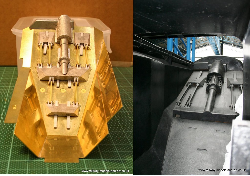
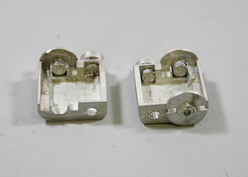
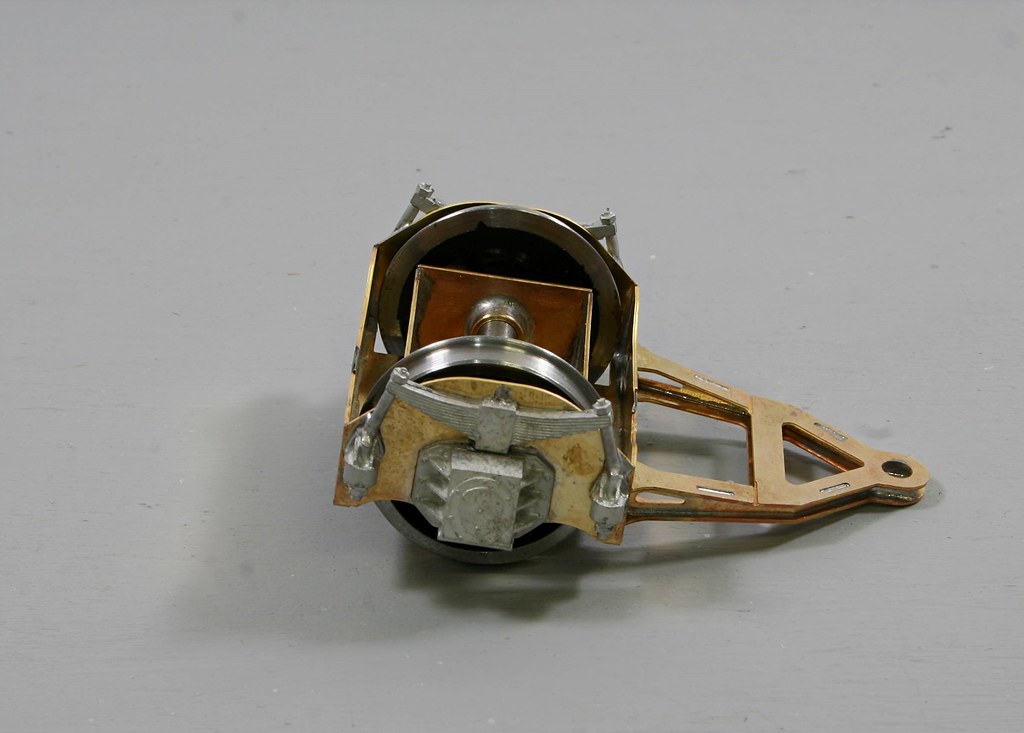
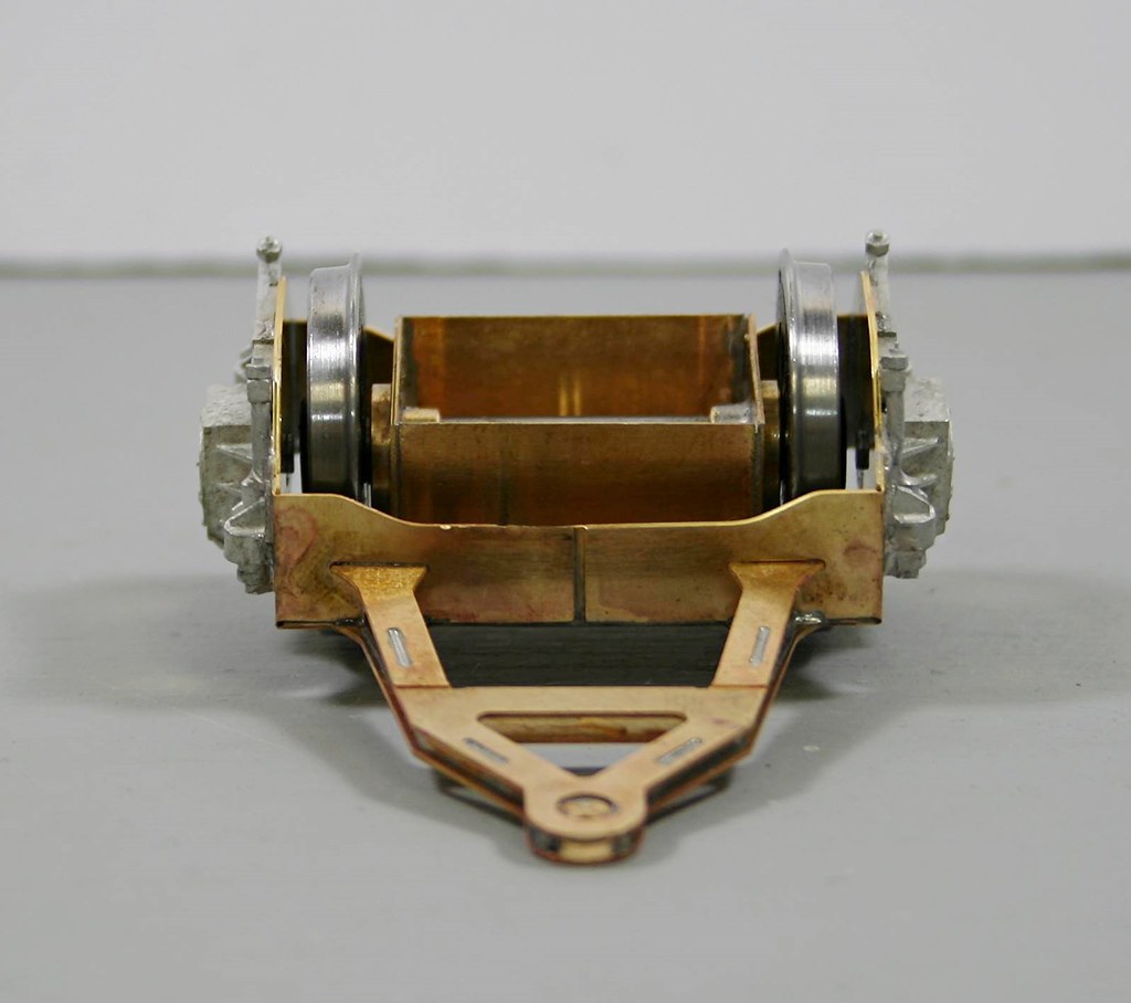
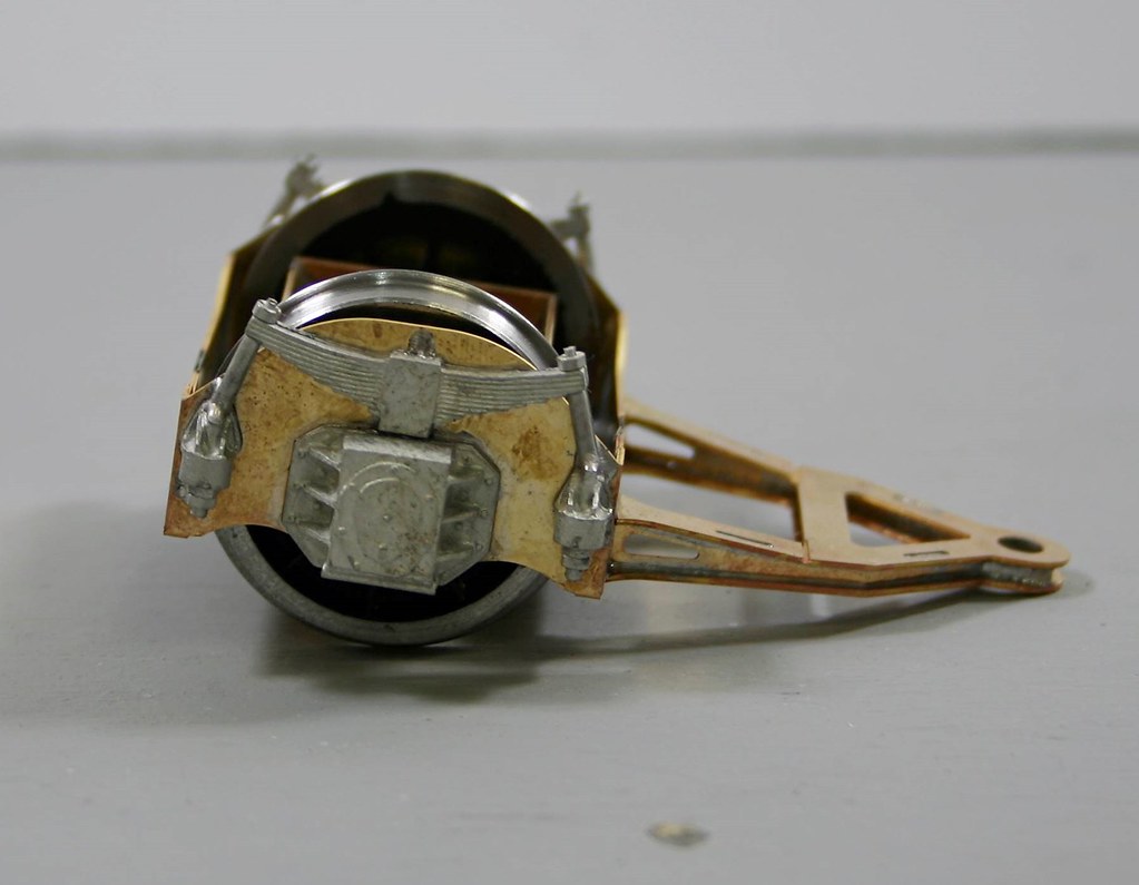
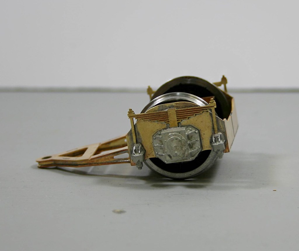
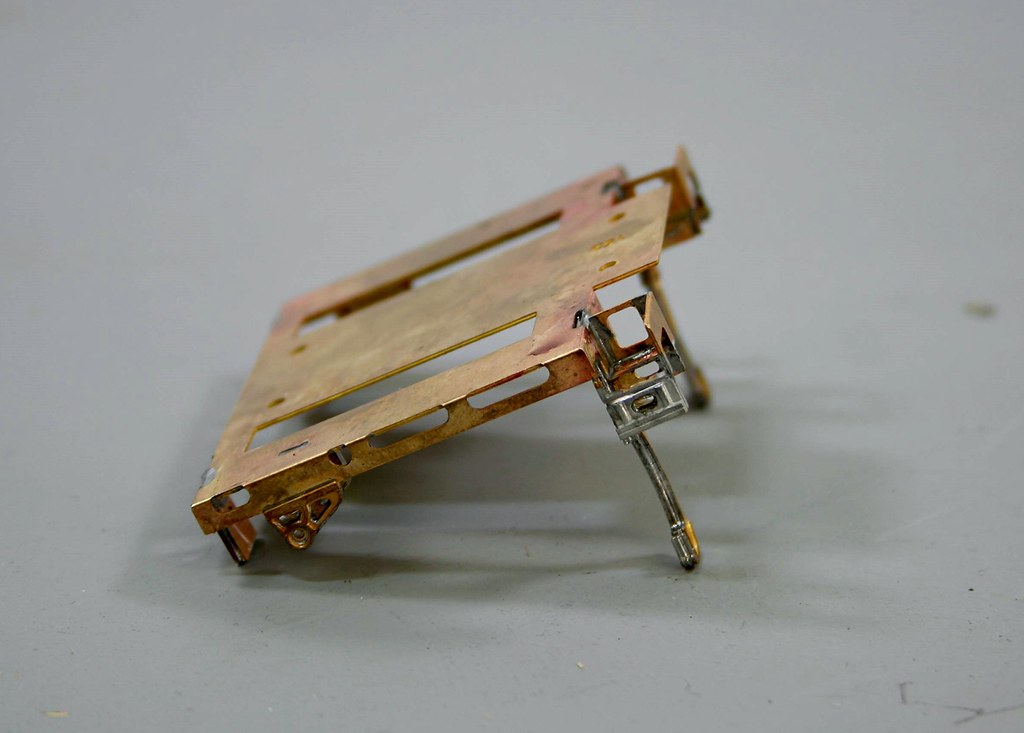
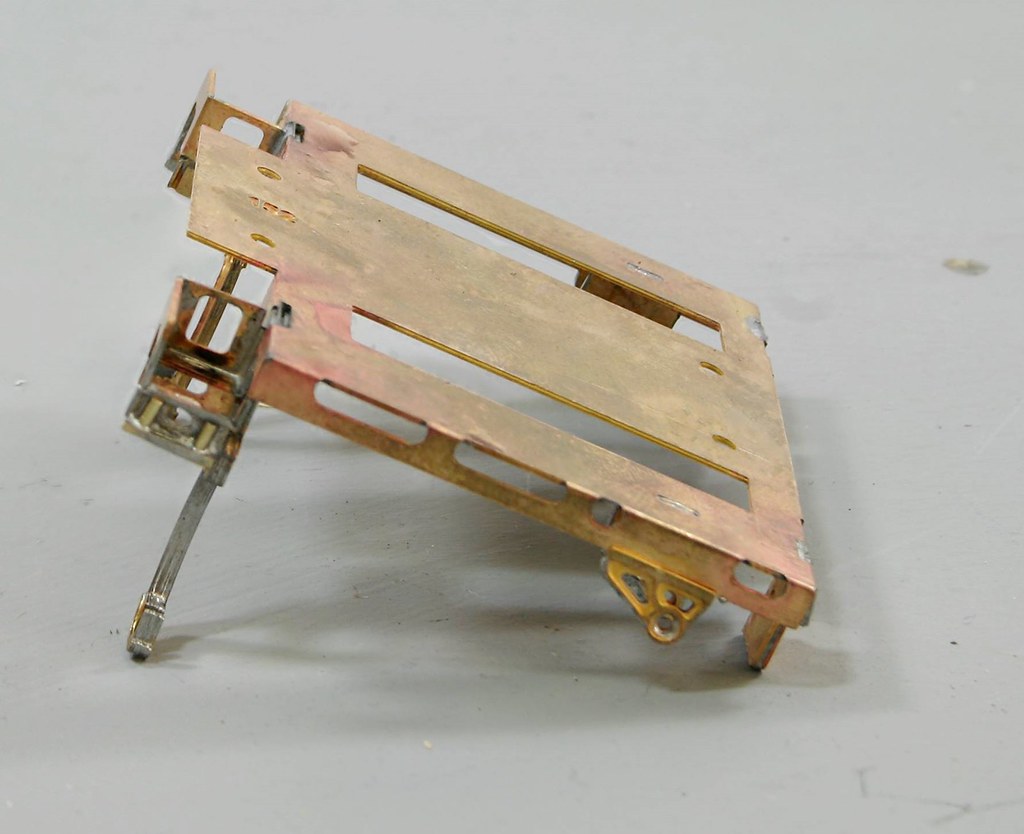
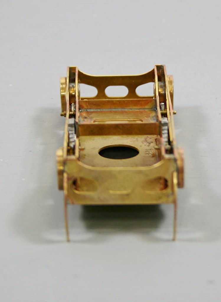
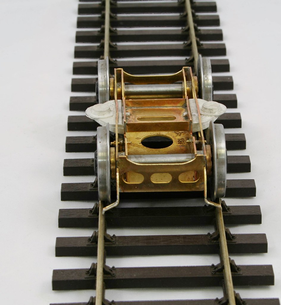
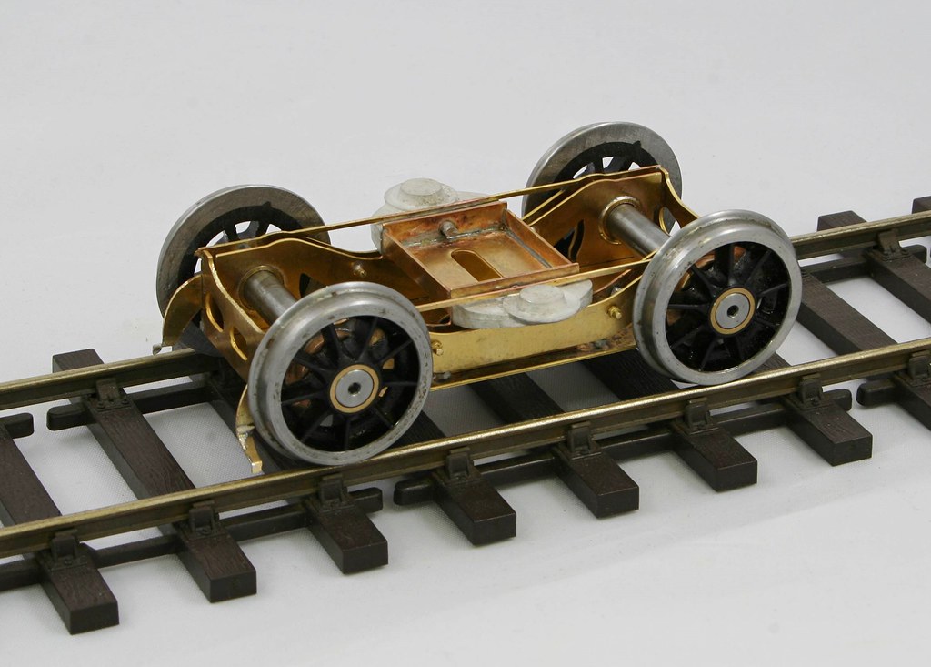
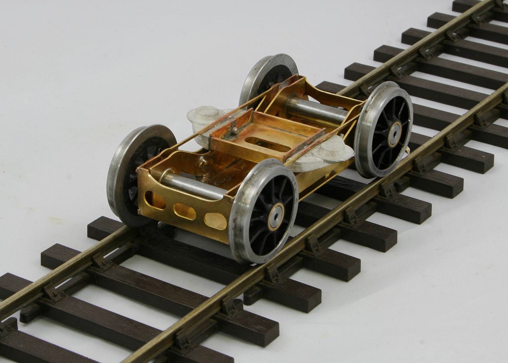
), I started on the bogie.
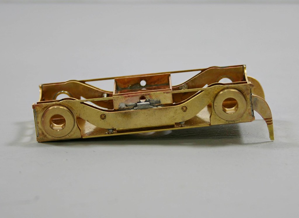
Sadly having rescued the and fitted the springs where they should go, you don't see much of them once it's assembled.

40022129530_7b70ecfe53_b.jpg


Now you see them....

41828659751_b79d28ec42_b.jpg


Now you don't....

41148415124_de3a8f50ae_b.jpg


41822757212_9ea7d2906b_b.jpg


41148414724_4d96f30799_b.jpg


I also made a start on the valve gear but more on that later.
 

Rob Pulham

Western Thunderer
Despite many distractions recently I have made slow progress on the Coronation.

One of the easier wins over the weekend was to epoxy the balance weights on - the instructions have you do this much earlier in the build but I seem to have a tendency to do them as late as possible and I am not sure why.

Then on to the fun bits, I wanted to make the valve gear removable for painting so some mods were needed

This is what the front of the frames looked like with slots where the cylinders fed through to attach to the top of the frame spacer.

42436637841_87d88cedd1_b.jpg


This was what they look like after a visit from my piercing saw.

28563675958_dd4e3d0f61_b.jpg


Then I needed to make some spacers to attach the two cylinders together

42436564221_d6df7b802a_b.jpg


Doing this meant that the 2mm diameter screws provided were not long enough so I retapped the holes 8BA and added some longer 8 ba screws. to hold them on.

next I soldered the slide bars to the motion bracket frame and started to assemble the valve gear

28563674788_795021a683_b.jpg


DJH provide 14ba screws/nut to assemble the valve gear which I have used but I have also done a belt and braces approach by tapping all the holes 14ba too which allows the nut to be locked on. Most of them also needed to be filed back for clearance purposes.

42436562831_0326c4453a_b.jpg


Last night I fitted the motor into the basic chassis and ran it for a while with the connecting rods attached. It was a good sign that nothing decided to unscrew itself while it ran (which can be a sign of something amiss).

Hopefully tonight will see the valve gear fitted and tested before stripping it back down ready for Warren to paint.
 

Rob Pulham

Western Thunderer
From "Woe to Recovery", it sounds like the title of a book or film

Where do I start, when assembling the cylinders, one of the jobs was to drill out the valve guides. When I drilled the first one I managed to break a drill bit of in the middle of it. I attempted to get it out by cutting off the rear spigot and drilling small holes around the end of the drill bit but didn't succeed in getting it out. I popped a bit of rod in the other end and it went a fair way in so I reasoned that I might get away with shortening the rod because the valve stems don't appear to move that much.

This was what was peeking out of the end of the casting but it wasn't quite enough to grip.

41567010675_c3f651b357_b.jpg


When I broke the drill bit off in the first casting, I decided to make a collet to allow me to better grip the second casting without damage and I was able to drill the second one without issue.
This is the collet and another view of my attempts to remove the offending drill bit stub

41746761294_38bc391d8d_b.jpg


I advised the gent that I am building it for what had happened and that we may need a spare casting but I was going to attempt to work my way past it. During the assembly of the valve gear I carefully measured the amount of valve stem and progressively shortened it until it fit.

Fast forward to giving it a test run and it dropped out of the guide jamming up the valve gear.
42469415881_1763c42da8_b.jpg


When this happened on Tuesday evening I took the wise course and stopped to ponder.

First thing yesterday morning as I was getting up for work, Chris said I have the solution to getting the drill bit out and proceeded to explain the idea that she had dreamt while asleep. The idea was basically, to cut a cut down the side of the casting to relieve the grip from the whitemetal and then drift the stub out.

After dinner I went into the workshop to take the valve gear to bits and unsolder the valve guide casting. I then out the casting in the collet and after a bit of a fiddle managed to get the seam of the casting lined up with the slit in the collet and gripped in the vice.

41567010895_958a905697_b.jpg


41746760784_63f3c60e1d_b.jpg


That done and using an old Exacto Blade, I proceeded to cut through the side of the casting using some odour free white spirit as a lubricant (made more essential by the fact that this Exacto blade has a slight kink at one end). I kept steadily cutting until I felt the blade grating on the side of the drill bit stub (why I used an old blade) and then removed the casting from the vice.

41567010495_9092512648_b.jpg


The next bit's I forgot to take photos of but using another broken drill bit as a drift I placed the bottom end of the casting on a block of wood which I have on my bench with the protruding stub of the drill over a hole that I had drilled when going through something previously (it doesn't quite look like swiss cheese but there are a good few holes in it).

The drift moved the drill bit out a few millimetres further, to the point where I was able to grip it in a pin vice. I was then able to grip the casting in my hand and a twist of the pin vice had it free.

41567010095_c3bb661d46_b.jpg


I then filled the seam with 70 degree solder and using the collet as a heat sink I soldered the casting back on and cleaned it up. In the photo below the seam is uppermost and is to all intents and purposes invisible.

41746762334_c395ef2cb4_b.jpg


Lastly I dismantled and remade the valve stem. The original is two layers of etch. I made the replacement from a piece of 1.10mm brass rod. I am not too happy with the boss so I plan to have another go later this morning.

This is the shortened version.
42469416761_61bf24a885_b.jpg


This is with the bit that I had cut off
42469416411_893060378a_b.jpg


Lastly this is the replacement.
41746761654_e2e605e019_b.jpg
 

P A D

Western Thunderer
Hi Rob,
I see you've been walking on water.

By the way, the expansion link is back to front in the photo showing the valve gear. Probably made no difference when you tested it, and I'm sure its is only fitted temporarily.

Cheers,
Peter
 

Rob Pulham

Western Thunderer
you really need to get that lathe up and running:rolleyes: - 11 out of 10 for perseverance though.:thumbs:

I couldn't agree more, I would have turned a replacement as a first choice.

The toolpost has been despatched from the US so it's a waiting game now and I am not sure how long things take to get here.
 

Rob Pulham

Western Thunderer
Hi Rob,
I see you've been walking on water.

By the way, the expansion link is back to front in the photo showing the valve gear. Probably made no difference when you tested it, and I'm sure its is only fitted temporarily.

Cheers,
Peter

Hi Peter,

It is, but thanks for pointing it out - the other side is the right way around
 

Rob Pulham

Western Thunderer
After Wednesday's woe today is Sunshine and Joy. She runs at last. There are a couple of the fixings to sort out but the motion all works as intended after my repairs. I still need to add the reversing shaft and the speedo but then I think that I am onto the body.


michael080

Western Thunderer
Rob,

just wondering, has the broken drill been a HSS-steel type or a carbide type?
I like to use the "soft" HSS drill bits for white metal, but I use them only with a pin vice.

Michael
 

Rob Pulham

Western Thunderer
Rob,

just wondering, has the broken drill been a HSS-steel type or a carbide type?
I like to use the "soft" HSS drill bits for white metal, but I use them only with a pin vice.

Michael

Hi Michael,

It was from one of those multi-boxes of drill bits (0.4-1.6mm) so the odds are that its the soft HSS type - I do have better quality drills in some of the sizes but not in the 1.2mm that it needed.
 
Top