Great Eastern E22 (J65) in gauge 3

geoff_nicholls

Western Thunderer
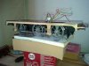
There has been some progress building the E22:
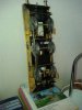
I bought a rolling road and used it to test the motor/gearbox in situ, Then adapted Mike Williams' hornblocks kit for this loco. They are designed to use a spring underneath, but the E22 had it's real springs underneath, so I tirned the hornblocks upside down. At rest the loco will sit of the tops of the screws on the outer axles, there will be 1mm play above the centre axle. The hornblock springs will push the axles down when the track dips.
I've tried running it on my track; an 0-6-0 with 13' 6" wheelbase, and 55mm width over the frames will happily negotiate 8' 0" radius turnouts, though there is no slack.
The photo also includes one of Mark Wood's wheels, as you can see he uses the same technique as Alan Gibson in 7mm. You may just make out the thin insulating tube around the stub axle.
It looks as though it is going to work nicely, but if anyone out there spots impending problems with the above, please let me know in good time.
 

geoff_nicholls

Western Thunderer
One Step Backwards, Two Steps Forwards.​
I don't think I mentioned earlier that I had changed how I intend to finish the coupling rods, originally I was planning to have the fluting ground out, but now I'm planning on etched nickel silver overlays. That means they are thicker, and the brass coupling rod bushes wouldn't be long enough.​
The original bushes provided by Mark Wood are threaded inside to match the M2 screws. I thought I could just replace these by longer sections of 3mm brass tube. I was wrong. The tube was too loose on the screw, and it was impossible to tighten the nuts without causing sufficient eccentricity to causing the coupling rods to bind.​
That's the main lesson I'd pass on to other beginners in this bit, the bushes should fit tightly on the coupling rod screws.​
I ordered a new set of threaded bushes. Having fitted these I tried it out again on the rolling road. Holding the motor up in my fingers, I could still feel a 'pull' with each rotation. I found one of the rods was slightly bent during soldering the layers of the steel rod together. (soldering steel is a nightmare!). And the layers were very slightly mis-aligned.​
The vice and a file seem to have fixed this.​
I cut some lengths of spring and fitted them loose on the hornblocks. It just about floats, but will sit firmly when the batteries are added. I think I will need to glue the springs vertically in place to stop them twisting.​
It now runs quite smoothly, though still not as smoothly as the 'Venture' loco Ken Cottle was demonstrating at the G3 AGM. Now I need to install batteries and RC and take it to GTG's to get some hands-on help from the experts.​
 

lancer1027

Western Thunderer
Hi Geoff,

Nice to see another modeller going the R/C route.:thumbs:

Is that an Easybuild DMU in the back ground;), if so i would love to see a workbench build especially if that too is going R/C.

Rob:)
 

AndyB

Western Thunderer
Rob,
In the G3 world, I would say that R/C is more common than 2 rail now.
No problem to run on the same track as live steamers, no track cleaning needed, etc. And, of course, plenty of room in all but the smallest locos to get the kit in.
My locos will all be r/c - when I finally get any built.......

Andy
 

geoff_nicholls

Western Thunderer
The DMU in the background is the GRS class 121 bubblecar. It will be electric RC. It is supplied with two motor bogies, but I'm thinking of building it with only one bogie powered
 

geoff_nicholls

Western Thunderer
The J65 is progressing slowly, the first stage, building an underframe controlled by RC, was successful, and the bits up to footplate level are being assembled. The brake gear will all fitted together with 12BA screws, so it can be disassembled for painting and maintenance. I don't have any milling tools etc so everything is etched in 0.018" brass layers soldered together. This is a bit fiddly. The brake blocks needed 8 layers. it was a useful exercise, to see if I could do it, but with the next loco, I might just ask for help from friends with the right tools.
The artwork for everything above the footplate is being drawn in turbocad, for etching, but I was waiting for the tubing for the boiler to get the exact dimensions.
It arrived ten minutes ago. It looks enormous! But I've measured it, and held it against the drawing and it appears correct. Hopefully sawing off the bit I need won't be too difficult, as it's brass.
 

AndyB

Western Thunderer
Come on Geoff - you know we like pictures!
How about a sneak preview of the etch artwork for the 'tin work'?

Andy
 

geoff_nicholls

Western Thunderer
Andy,
there's lot of work needed to turn it into 'artwork'. I'll be using my local etching service instead of G & H. They are more expensive, but do a very quick turnaround. And I've got to squeeze it all into A3 size. if I'm careful I can arrange it as two copies of one plate.

I do have one query, how big should I draw a 1mm dia hole? this is 0.018" (0.46mm) when I've drawn 1mm dia holes before, they've been a bit slack, so I'm guessing 0.8mm would turn out right.

Once the artwork is done, I'll post a PDF.
 

geoff_nicholls

Western Thunderer
In the meantime, here's the underside. I opted for the Tamiya charger socket, which is probably a mistake.
The crossbeams at the bottom of the hangers are 1.5mm brass tube. I was filing down headless 12BA screws to fit in the ends, but I found the heat from the soldering iron expands the tube and the bolts fit nicely (is that what is meant by 'sweating something on'?)
 

Attachments

  • 20150310_141828.jpg
    20150310_141828.jpg
    193.9 KB · Views: 52
  • 20150310_141739.jpg
    20150310_141739.jpg
    126.1 KB · Views: 56

AndyB

Western Thunderer
I do have one query, how big should I draw a 1mm dia hole? this is 0.018" (0.46mm) when I've drawn 1mm dia holes before, they've been a bit slack, so I'm guessing 0.8mm would turn out right.
Etch factor of 15% of metal thickness is the basis for what I use.
So your 1mm nominal hole should be drawn at 1-(2x0.15x0.46) = 0.86mm. At 0.8mm I think you'll end up reaming out every single hole to size (unless it gets badly over-etched!).

The Tamiya charger does look a bit 'chunky'. I think most people use 2.1mm sockets (me included) - which is convenient if you need to borrow a charger having forgotten to either charge up the loco or take your own when visiting other lines (as happened to me only last weekend with Thomas' first outdoor outing!). They also fit in much neater.

Andy
 

geoff_nicholls

Western Thunderer
taking Andy's advice, I bought a couple of 2.1mm plugs from Maplin.
Is there a standard people follow when connecting it to the battery?
 

AndyB

Western Thunderer
Geoff,
I use centre-pin positive - which follows what Cliff Barker shows in his instructions, IIRC.

Andy
 

geoff_nicholls

Western Thunderer
Some more progress on my first scratch built gauge 3 loco. I couldn't upload a PDF of the etching artwork as the file was too large, but I don't think it showed any innovative thinking on my part. my first 7mm loco was a Connoiseur kit of the same loco, and I've pretty much copied what I remember of that. The boiler was cut from 60mm dia brass tube, using a printed CAD drawing glued on as a template.
My current thinking for the boiler fittings is to produce CAD artwork and have them 3D printed. Then possibly have a batch cast in brass, if anyone else needs GER chimneys and domes in gauge 3?

On the subject of PDFs and etching, for anyone new to producing artwork for etching; Grainge and Hodder send you a PDF of your artwork, showing exactly what will come out of the etching process, then do the job once you've confirmed it's correct.
This overcomes the uncertainty when using a different CAD tool to theirs, and highlights anything you've forgotten, even though you'd checked the original artwork several times over.
 
Last edited:
Top