Pugsley
Western Thunderer
After a lot of admiring from a distance, I finally took the plunge into 7mm scale late last year. I managed to hold off actually building the kit for some time, until I finally crumbled earlier this year...
The kit isn't going to be built quite according to the instructions though - part of the inspiration for my foray into 7mm was Chris Pendleton's fully sprung Deltic. If it can be done in 4mm scale, I thought, I should be able to do it in 7mm - with the added twist of individual traction motors...
So, I am now at the stage where the first design of bogie parts has been received from the etchers and I'm currently playing with the parts and working out what's right and what needs a bit of work. I've started working on the Mk2 design, which is mostly the original parts tweaked slightly.
So, on to the photos of progress so far:
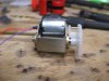
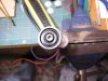
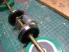
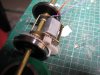
I've made the new axles, from 3/16 silver steel which are in two halves. The idea being that, once the traction motor assembly is installed on the axle, it is going to be quite difficult to set the back-to-back measurements accurately. In order to do this, and take account of any error in the manufacture of the axles, the two halves will screw into each other. The wheels will be an interference fit on the end of the axles (reamed 4.74mm), adding to the need to make the axles adjustable.

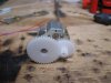
At this stage, i still need to tap one half and run the die over the other. I've used M3 on the axles. The final drive gears have been drilled and reamed to 4.74mm, again for an interference fit on the axles.
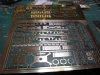
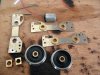
As mentioned above, I've also been playing with the initial design of bogie parts. There is a little more work to do here, but the basics are below.

The functional frame of the bogie is etched in 0.70 NS - the JLTRT sideframes have had the axleboxes carefully cut away with a piercing saw, which have been set aside for later. I'll drill and tap the sideframes, probably 10BA, and insert studding where the screws are. The cosmetic frames will be secured with nuts inside the cross-members. Milled down Slaters Hornblocks will run in the cut-outs, which need guides adding (something I left off the original design ) It also gives an idea of how the secondary suspension mounts are secured to the cross-members.

The brake gear will be hung from these projections on the cross-member, with the exception of the outer ends, these will be located in the moulded brackets on the JLTRT bogie frame - these will be carefully cut from the moulding.

I've added bearing plates to the chassis (that don't quite fit properly ATM), which the secondary springs will bear on. The part you see in the pic will be redesigned slightly to incorporate screwed adjustment to the secondary suspension. The central mount in the pic above isn't in quite the right order, but serves to demonstrate the method of transmitting the tractive effort to the 'kingpin'. The circular washer will fit around the stud secured in the chassis floor. These will be stacked up to the necessary ride height, and will locate into the square surround, soldered to the bolster. This will be composed of two layers of 0.7mm material, which should give enough latitude for the bogie to move around, without excessive slop.
That's enough of the technical stuff - I've also been doing a bit to the body, including capturing that elusive rippled effect (this isn't the best picture in the world, but it gives you an idea - it's a very hard effect to capture well on a photo!) :

One side needs a little more work - the effect is a little too subtle at the moment, but I'm trying to concentrate on the bogies at the moment. I was hoping to have one ready for Telford, but I don't think I'm going to manage that now. The next elastic deadline is the S7 gathering at Mark in October
The kit isn't going to be built quite according to the instructions though - part of the inspiration for my foray into 7mm was Chris Pendleton's fully sprung Deltic. If it can be done in 4mm scale, I thought, I should be able to do it in 7mm - with the added twist of individual traction motors...
So, I am now at the stage where the first design of bogie parts has been received from the etchers and I'm currently playing with the parts and working out what's right and what needs a bit of work. I've started working on the Mk2 design, which is mostly the original parts tweaked slightly.
So, on to the photos of progress so far:
I've made the new axles, from 3/16 silver steel which are in two halves. The idea being that, once the traction motor assembly is installed on the axle, it is going to be quite difficult to set the back-to-back measurements accurately. In order to do this, and take account of any error in the manufacture of the axles, the two halves will screw into each other. The wheels will be an interference fit on the end of the axles (reamed 4.74mm), adding to the need to make the axles adjustable.
At this stage, i still need to tap one half and run the die over the other. I've used M3 on the axles. The final drive gears have been drilled and reamed to 4.74mm, again for an interference fit on the axles.
As mentioned above, I've also been playing with the initial design of bogie parts. There is a little more work to do here, but the basics are below.
The functional frame of the bogie is etched in 0.70 NS - the JLTRT sideframes have had the axleboxes carefully cut away with a piercing saw, which have been set aside for later. I'll drill and tap the sideframes, probably 10BA, and insert studding where the screws are. The cosmetic frames will be secured with nuts inside the cross-members. Milled down Slaters Hornblocks will run in the cut-outs, which need guides adding (something I left off the original design
) It also gives an idea of how the secondary suspension mounts are secured to the cross-members.The brake gear will be hung from these projections on the cross-member, with the exception of the outer ends, these will be located in the moulded brackets on the JLTRT bogie frame - these will be carefully cut from the moulding.
I've added bearing plates to the chassis (that don't quite fit properly ATM), which the secondary springs will bear on. The part you see in the pic will be redesigned slightly to incorporate screwed adjustment to the secondary suspension. The central mount in the pic above isn't in quite the right order, but serves to demonstrate the method of transmitting the tractive effort to the 'kingpin'. The circular washer will fit around the stud secured in the chassis floor. These will be stacked up to the necessary ride height, and will locate into the square surround, soldered to the bolster. This will be composed of two layers of 0.7mm material, which should give enough latitude for the bogie to move around, without excessive slop.
That's enough of the technical stuff - I've also been doing a bit to the body, including capturing that elusive rippled effect (this isn't the best picture in the world, but it gives you an idea - it's a very hard effect to capture well on a photo!) :
One side needs a little more work - the effect is a little too subtle at the moment, but I'm trying to concentrate on the bogies at the moment. I was hoping to have one ready for Telford, but I don't think I'm going to manage that now. The next elastic deadline is the S7 gathering at Mark in October
 will you be able to pin the gears to the axle? Im not sure I would entirely trust a glued joint in the drive train
") )
)
 the heat seems to soften the moulding, mind you I did it with a spoked wheel as well- still you only do it once. Are you not tempted to ballrace the gearbox? I have a source for flanged bearings that would probably fit.