7mm LNER N1 0-6-2T Ace Products Kit

SimonME30

Member
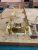
Wish me luck, I’ve had this kit for a few years, and the reviews aren’t promising. An aide to scratch building is all that it’s supposed to be, and I’ve done some of that previously...so this is my COVID-19 project. I’ve had a reasonable search, but not come up with anybody else’s build, so if there is one documented out there please point me in the right direction.

I’m armed with a Yeadons register, the brief instructions do include drawings, and I have decided on 69434 as there is a photo of the loco at Bradford (Exchange), it was allowed to Bradford from 24/6/1951-27/1/57 and scrapped 10/3/1959 from Copley Hill. So a high chance of being caught at Bradford (Exchange) during my 1954-1959 Modelling period.

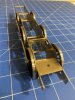
I’m interested in operations rather than exacting model engineering, and I’m heading for battery powered/radio control. It will be a rigid chassis, as I’m not worried about pickups, and my other rigid chassis builds seem fine on my layout.

I’m posting in the hope that a) I’ll be half kept honest to keep progressing, and b) helpful suggestions will be offered!

Pics to come as soon as I work that out on the iPad...
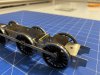
 

SimonME30

Member
Kit as received. Nice box..thought I’d try a mobile modelling desk to be a bit more sociable..I’m working from home in the guest room out the back, so thought sitting inside and modelling of an evening might be nicer.48EC1FF0-3FA1-40E8-99FD-F9E469393542.jpeg
Chassis looks reasonable in nickel silver.
776EB11F-A81E-4D7C-96DB-DDA7769A0F19.jpeg
End of modelling session number 2. I’ve made up the coupling rods, and made them jointed, despite the rigid chassis plan. Hobby holidays master chassis jig getting a test run. I don’t like the chassis spacers, and the instructions are pretty sparse. There is nothing in the vertical plane to keep the frames vertical. I’d really like something that represented the cylinder block, and the motion frames? I’ve been hunting for a GA for an N1 or N2 to provide some indication, but haven’t pulled anything up yet. I thought I’d take a look at the footplate to see where the Cylinder block should end, and folded up the smoke box saddle as a starting point. I saw a video tonight of a 7 1/4” N2 and if it’s similar to an N1, that spacer between the front drivers and the middle drivers shouldn’t be there. Whilst not wanting to go overboard, I might as well use chassis spacers which mimic the full size.

42D07BE2-49A2-415F-8E0D-3063AAA4D2F2.jpeg
 

Susie

Western Thunderer
Hi Simon,

The N2 is an updated version of the N1 and rather different in the cylinder and valve gear. The N1 has slide valves between the cylinders, whereas the N2 has piston valves above the cylinders driven by rockers, which is the reason for the increase in boiler pitch. The cylinders are directly underneath the smokebox. About a third of the way from the cylinders to the driving axle is a beam which carries the valve spindle guide block, and further back again is the motion plate which supports the ends of the slidebars (four per cylinder) and the bracket for the weighshaft which is below the eccentric rods. In the N2, the basic layout is similar except the motion plate also carries the supports for the rockers which are behind the expansion links.

Susie
 

SimonME30

Member
Ext bit of fun. Smoke box saddle in position. I have no idea how I could get 0.5mm scrap hard brass from the side of the etch to roll up to form the sides of the saddle, per the instructions.

moving along then. Sandboxes have their fold lines marked on the outside of the bends. That looks a bit odd. And when the splashers are lined up with the cutout in the footplate, there is a big gap where they should butt up to the front frame extensions (which aren’t provided for). The drawings show that the outer dimension of the splashers should be 39mm but the distance between the cutouts in the footplate is 44mm. Hence the 2.5mm gap either side between the sandboxes and the smoke box saddle. Hmm. And I don’t like my chances of bending up a nice piano front for the valve covers out of the chunky bit of brass supplied, which does match the width of the smoke box saddle at least (it’s a bit wide to the drawing).
 

Attachments

  • A22FA4C6-F076-40C2-BD0F-1E423C0971A3.jpeg
    A22FA4C6-F076-40C2-BD0F-1E423C0971A3.jpeg
    126.2 KB · Views: 63

Susie

Western Thunderer
Hi Simon,
There isn't actually a saddle on the N1. The one in the kit must be just for "ease of construction" (sic!). Most of it will be hidden though by the cover plate in front of the cylinders The smokebox wrapper comes round and is fitted to the top of the frames - or they would if the kit ones were the right shape!

The model is coming on though, well done!

Susie
 

SimonME30

Member
Doesn’t look like progress, but I think I’m moving forward.

thanks to info provided by Susie, I’ve worked out my chassis spacer strategy. I’ve done some workings in Inkscape to design the individual elements. None of which will be visible!

I’ve cut the splashers down to width, decided that the smoke box ‘saddle’ should actually be part of the boiler rather than the footplate. So it’s been unsoldered and cleaned up.

live also bent the ‘frame extensions’ back down flat - they are too far off centre and throwing the splashers out.
4BA1EB21-CBDE-4334-8E77-DE735D98F994.jpeg
Saddle unsoldered. Wanting to see where the splashers should finish up, tops of the sandboxes should be next to the boiler.
3B0444BB-1ED5-4C5F-AFC8-CB8F01EA34BE.jpeg
Frame extensions folded back down. Gives me half a chance to get those splashers in the right place. Back to the frames next
 

SimonME30

Member
I’ve been framed.

That chassis jig is a good bit of kit. Turned by hand just fine, straight off the jig, and then stiffened up. Odd...I made the large frame spacers emulate the cylinder block. I’m tempted to buy the lost wax inside motion option from Ace Products, just to see what stiffening can be achieved.
903B013E-A0A5-411B-9FBB-6F3F37C0584D.jpeg
 

SimonME30

Member
Why is it that you spend a chunk of time to make something that won’t be seen? Anyway, motion plate made up, because the chassis has minimal bracing. And so it’s not the smoothest chassis yet. I’m pondering a faux ash pan to provide some more rigidity. Then run in the bearings a bit with some steel rod, jiff and the battery drill....
 

Attachments

  • 6D4426EB-7D26-4357-931E-7A63F8476E80.jpeg
    6D4426EB-7D26-4357-931E-7A63F8476E80.jpeg
    125.3 KB · Views: 15
  • 69BB19FF-52C2-4229-9762-E906C8D98BE9.jpeg
    69BB19FF-52C2-4229-9762-E906C8D98BE9.jpeg
    173.3 KB · Views: 16

Scale7JB

Western Thunderer
Simon, I'm afraid from my experience if a chassis doesn't run perfectly first time without running in, there's something wrong with it. If you need to ware it in, it'll be worn out before you start.

However, it's always worth running a 3/16" reamer through the bearings to ensure they are the correct internal size. There does require a small amount of engineering precision when building a chassis. Can you measure with a set of vernier callipers the distances between the openings for the bearings to see if they match from side to side?

JB.
 

Scale7JB

Western Thunderer
Another tip is to look down from directly above to see if the backs of the wheels are parallel to the frames. If not the frames are out - OR - the brass hub in the wheels is out which can happen.

Take the wheels and spin by hand on a sheet of glass on some fine sand paper. This will ensure the hub is in line with the rest of the wheel. I need to do this on some wheels later so if you're not sure on this I can do a video.

JB.
 

mickoo

Western Thunderer
Couple of handy hints, the hobby holidays jig, whilst good, can lead you astray with axles not perfectly parallel. This is down to the design and the way the adjustment screws work, basically the blocks have a little wriggle room on the guide bars.

You've mounted your jig axles with the stubs for the coupling rods on the inside, you'll get better accuracy if the axles are turned and the rods on the outside of the fame, use the rods to set the axle distance then simply take them off, no need to keep them on there once the jig is set.

When I set mine up I leave the rods on and then tweak the adjustment screws, you'll find that the part of the axle nearest the fixing block can still move quite a bit, I measure the gap between each rod at the tip near the coupling rods and then again near the fixing blocks, it's important to make sure they are parallel.

At a random guess, I'd say your chassis is tightening up when one, or even both, sets of coupling rods are at 3 or 9 'o'clock, in which case you will need to tweak the crank pin holes in the coupling rods.

You're using Slaters wheels, it is common for them not to be mounted square on the end of the shaft, the 'wobble' will throw the crank pin out as well, I've also had crank pins not square or straight either.

So, before you attack your bearings with jiff and a steel rod in a drill (really not a good idea anyway ;)) take the coupling rods off and run the chassis along by hand, if it's still tight then it'll be a wheel/bearing issue, if it's free, then there's a very high chance it'll be crank pins or coupling rods.

Finally, as JB notes, invest in a 3/16" reamer, it's essential for making your life easier when chassis building :thumbs:
 

oldravendale

Western Thunderer
I had exactly that problem when using the Hobby Holidays jig on the "K". When I tried some long ground bars through the bearings (granted this having been suggested by Steph!) the lack of parallelism became quite apparent. Removal of one of the hornblocks and then reinstalling settled the issue once and for all.

I now use the jig as described by Mick above.

Brian
 

SimonT

Western Thunderer
All the Finney7 instructions carry Martin's recommendation to use long rods through the bearings and to place the chassis over a piece of graph paper. This will instantly show up bearings that aren't aligned and bearings that aren't seated true to the chassis. If you have no graph paper, draw a series of parallel lines on the computer and print them off.
Simon
 

Dikitriki

Flying Squad
I made a modification to my Hobby Holidays jig. I turned spigots for the couping rods on t'other end of the axles, and am therefore able to check parallelism by fitting the coupling rods on both ends at the same time. This assumes a) you have access to a lathe, and b) you can make 2 x identical sets of rods.

Richard
 

SimonME30

Member
Wow, excellent suggestions, really appreciate the guidance. Funnily enough, previous Locos have been done using long rods....I changed the jig around as suggested. I have a lathe, and am inclined to turn down the other ends of the rods.

I had pulled the outer block screws up a touch, so put everyone back on the chassis jig, with them eased. Gave the bearings a quick touch with the gas torch again. Success! It slid easily of the jig, and ran like a dream, with the rods on.

and now it has stiffened up again, after a bit of rolling to and fro on a decent size cutting mat. So I’m thinking too much chassis flex. I tried it on the layout, and a crank pin but came off. Washer lost, so I’ll need to find my supply of spares.
 

Scale7JB

Western Thunderer
Are the backs of the wheels parallel to the frames? Is there any oscillating in the wheels when looking from above?

JB.
 
Top