You are using an out of date browser. It may not display this or other websites correctly.
You should upgrade or use an alternative browser.
You should upgrade or use an alternative browser.
P A D
Western Thunderer
Hi Mick,
Thanks. It would be good to see some photos, but they are on now and I'm happy with them. I'll check the ones I took of Bittern after it had just been restored at the Mid Hants but I don't think I got any underneath.
What do you make of these? They are Laurie Griffin's. The equalising beam looks more like the Hobbyhorse ones but less chunky.

Cheers,
Peter
Thanks. It would be good to see some photos, but they are on now and I'm happy with them. I'll check the ones I took of Bittern after it had just been restored at the Mid Hants but I don't think I got any underneath.
What do you make of these? They are Laurie Griffin's. The equalising beam looks more like the Hobbyhorse ones but less chunky.
Cheers,
Peter
mickoo
Western Thunderer
Peter, those castings are close but no cigar.
What you need is this, Mallard

Copyright, mine.
Not a very good shot as the weather plate covers the salient details of the spring and fixing plate.
A better shot is this from a BLP at Peterborough.

Copyright, mine.
The only difference, as far as modellers need concern themselves are the two webs at the top (circled white), even then your talking minute shape differences in 7mm scale. On the Bulleid engines the web is straight and slightly higher. The other difference are the axle box retention rods, there being two rods on the BLP much like the A3/A4 Cartazzi axle box retention rods; The LNER bogie relies on a simple single flat bar.
Flying Scotsman, York.

Copyright, some geezer on the web.
A better image but not close enough to discern the details, though the web shape can be seen, lower and curves around the spring tie rod nuts.
Mallard has as far as I know the most authentic components being preserved and untouched since preservation, note the equalising beam pocket for the axle box stub is only ½ height (60007 is the same), that on the BLP and A3 being full height, my gut feeling is that the A3 has had replacement parts and the full height pocket was not fitted originally.
It's worth noting that the fixing plates with horn cheek are not one component but two individual castings, this from 60007 and is identical to the A3


Copyright, my secret agent deep inside NRM") , don't worry agent X, your identity remains safe
, don't worry agent X, your identity remains safe 
These show clearly the swept flange on the LNER fixing brackets.
For the W1 I'm using the BLP casting.

It has no web so can be used for LNER or SR if you're so inclined, the web could be added for either variant if you so wished. you also need to remove the two axle box retention rods, I didn't, not for the test build anyway.
Don't forget to add the side control spring weather plate, it's fitted to all the LNER engines, it's that plate in the middle of the bogie and wraps around to the underside; I've only added the front one on the above test build as I realised I'd fitted it wrong.
The riveted strip is not on top but should face forward/backward, on the real engine you can barely get on to that top plate, so removing the cover on shed for spring checks would of been impossible. The bottom is however riveted to the base of the bogie.
MD
What you need is this, Mallard
Copyright, mine.
Not a very good shot as the weather plate covers the salient details of the spring and fixing plate.
A better shot is this from a BLP at Peterborough.
Copyright, mine.
The only difference, as far as modellers need concern themselves are the two webs at the top (circled white), even then your talking minute shape differences in 7mm scale. On the Bulleid engines the web is straight and slightly higher. The other difference are the axle box retention rods, there being two rods on the BLP much like the A3/A4 Cartazzi axle box retention rods; The LNER bogie relies on a simple single flat bar.
Flying Scotsman, York.
Copyright, some geezer on the web.
A better image but not close enough to discern the details, though the web shape can be seen, lower and curves around the spring tie rod nuts.
Mallard has as far as I know the most authentic components being preserved and untouched since preservation, note the equalising beam pocket for the axle box stub is only ½ height (60007 is the same), that on the BLP and A3 being full height, my gut feeling is that the A3 has had replacement parts and the full height pocket was not fitted originally.
It's worth noting that the fixing plates with horn cheek are not one component but two individual castings, this from 60007 and is identical to the A3
Copyright, my secret agent deep inside NRM
, don't worry agent X, your identity remains safe These show clearly the swept flange on the LNER fixing brackets.
For the W1 I'm using the BLP casting.
It has no web so can be used for LNER or SR if you're so inclined, the web could be added for either variant if you so wished. you also need to remove the two axle box retention rods, I didn't, not for the test build anyway.
Don't forget to add the side control spring weather plate, it's fitted to all the LNER engines, it's that plate in the middle of the bogie and wraps around to the underside; I've only added the front one on the above test build as I realised I'd fitted it wrong.
The riveted strip is not on top but should face forward/backward, on the real engine you can barely get on to that top plate, so removing the cover on shed for spring checks would of been impossible. The bottom is however riveted to the base of the bogie.
MD
Last edited:
P A D
Western Thunderer
Here's a better shot of the inspection covers on the valve box and front of the running plate. It's not mentioned in the instructions but you need to scribe the smaller cover as it is not half etched, and the larger etched ones need the grooves extending to the edge of the running plate.

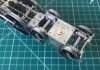
Back to the bogie. All the soldering is done and the cast springs added. The space for the slider can be seen and the inner surface were rubbed smooth and polished, as was the sliding brass block.

And from the other side just to confirm the springs are all the right way round.

And with the slider block, side control springs and the top screwed on.

The bogie pivot is fastened to the spacer with a 6BA bolt and will be soldered later.

And with the bogie in place. I gave it a push around the biggest curve on my brother's layout and it seemed OK. The cartazzi needs some attention though.
At the moment the spring lifts the front driving wheels as there is not enough weight to keep them down.

And a full length view of the chassis underside.

Cheers,
Peter
Back to the bogie. All the soldering is done and the cast springs added. The space for the slider can be seen and the inner surface were rubbed smooth and polished, as was the sliding brass block.
And from the other side just to confirm the springs are all the right way round.
And with the slider block, side control springs and the top screwed on.
The bogie pivot is fastened to the spacer with a 6BA bolt and will be soldered later.
And with the bogie in place. I gave it a push around the biggest curve on my brother's layout and it seemed OK. The cartazzi needs some attention though.
At the moment the spring lifts the front driving wheels as there is not enough weight to keep them down.
And a full length view of the chassis underside.
Cheers,
Peter
Attachments
mickoo
Western Thunderer
It has been known for some people to mount them upside down.................And from the other side just to confirm the springs are all the right way round.


Dikitriki
Flying Squad
It has been known for some people to mount them upside down.........

I note you didn't post that until after I'd paid your expenses
")
mickoo
Western Thunderer
Even with.....With friends like you Mick.......
lol, I've done far far worse and much of it unrecoverable, like two left sides to a 'particular' tank engine, or a set of frames 1mm too wide, fine for S7 but totally useless for the designed OF
I note you didn't post that until after I'd paid your expenses
Lancastrian
Western Thunderer
lol, I've done far far worse and much of it unrecoverable, like two left sides to a 'particular' tank engine, or a set of frames 1mm too wide, fine for S7 but totally useless for the designed OF
Hmm, and you might be doing some frames for me ?

)") Ian
Ianmickoo
Western Thunderer
That's why I always do a test etchHmm, and you might be doing some frames for me ?
at least it was consistently wrong, all 40 odd pieces .Mind, you model in S7 I think, so it would of been perfect
Anyway I'll let Peter have his thread back now after my hijack P A D
Western Thunderer
Peter, those castings are close but no cigar.
What you need is this, Mallard
View attachment 85025
Copyright, mine.
Not a very good shot as the weather plate covers the salient details of the spring and fixing plate.
A better shot is this from a BLP at Peterborough.
View attachment 85024
Copyright, mine.
The only difference, as far as modellers need concern themselves are the two webs at the top (circled white), even then your talking minute shape differences in 7mm scale. On the Bulleid engines the web is straight and slightly higher. The other difference are the axle box retention rods, there being two rods on the BLP much like the A3/A4 Cartazzi axle box retention rods; The LNER bogie relies on a simple single flat bar.
Flying Scotsman, York.
View attachment 85023
Copyright, some geezer on the web.
A better image but not close enough to discern the details, though the web shape can be seen, lower and curves around the spring tie rod nuts.
Mallard has as far as I know the most authentic components being preserved and untouched since preservation, note the equalising beam pocket for the axle box stub is only ½ height (60007 is the same), that on the BLP and A3 being full height, my gut feeling is that the A3 has had replacement parts and the full height pocket was not fitted originally.
It's worth noting that the fixing plates with horn cheek are not one component but two individual castings, this from 60007 and is identical to the A3
View attachment 85036
View attachment 85037
Copyright, my secret agent deep inside NRM
These show clearly the swept flange on the LNER fixing brackets.
For the W1 I'm using the BLP casting.
View attachment 85039
It has no web so can be used for LNER or SR if you're so inclined, the web could be added for either variant if you so wished. you also need to remove the two axle box retention rods, I didn't, not for the test build anyway.
Don't forget to add the side control spring weather plate, it's fitted to all the LNER engines, it's that plate in the middle of the bogie and wraps around to the underside; I've only added the front one on the above test build as I realised I'd fitted it wrong.
The riveted strip is not on top but should face forward/backward, on the real engine you can barely get on to that top plate, so removing the cover on shed for spring checks would of been impossible. The bottom is however riveted to the base of the bogie.
MD
Hi Mick,
You mention removing the two axle box retention rods. What are these?
Cheers,
Peter
mickoo
Western Thunderer
They're two bars under each axle box on the SR bogie casting, the Ragstone one doesn't have them....correctly for the LNER.
There's also two bars under the Cartazzi axle box which you have already added....correctly.
The Finney7 bogie axle box casting also has these bars as they were used on the SR, but not the LNER. To convert the F7 bogie axle box casting you need to cut them off.
The axle box is also very similar to that fitted to the A7 in LNER days, I haven't trimmed the retention rods off those either, as it's a test build to just make sure the parts fit.

Cut the casting at the red line and then add a simple flat bar as you would for a wagon W hanger say.
There's also two bars under the Cartazzi axle box which you have already added....correctly.
The Finney7 bogie axle box casting also has these bars as they were used on the SR, but not the LNER. To convert the F7 bogie axle box casting you need to cut them off.
The axle box is also very similar to that fitted to the A7 in LNER days, I haven't trimmed the retention rods off those either, as it's a test build to just make sure the parts fit.
Cut the casting at the red line and then add a simple flat bar as you would for a wagon W hanger say.
john lewsey
Western Thunderer
Hi Peter your A3 really is rather nice
John
John
P A D
Western Thunderer
Thanks Mick. Now it's clear.
Thanks John for the compliment. Long way to go though.
Decided to go back to the body and get the two boiler sections rolled. This is the parallel section. It has a neat joining strip for the joint which incorporates two of the boiler bands cleats.

The cleats fold up on the joining strip and fit through slots in the boiler.

The rear former.

And the front smoke box ring which is a 2 piece laminate. The holes in the outer ring are only half etched on the inside and need drilling through. This allows for those loco which had the handrails cut short and the pillars removed from the smoke box ring.
And with a couple of drill bits to line up the outer ring before soldering.

Here are the two sections completed. The coned part has a similar joining strip but with only one set of cleats.

And the two screwed together.


And sat on the running plate.

Next will be the firebox.
Cheers,
Peter
Thanks John for the compliment. Long way to go though.
Decided to go back to the body and get the two boiler sections rolled. This is the parallel section. It has a neat joining strip for the joint which incorporates two of the boiler bands cleats.
The cleats fold up on the joining strip and fit through slots in the boiler.
The rear former.
And the front smoke box ring which is a 2 piece laminate. The holes in the outer ring are only half etched on the inside and need drilling through. This allows for those loco which had the handrails cut short and the pillars removed from the smoke box ring.
And with a couple of drill bits to line up the outer ring before soldering.
Here are the two sections completed. The coned part has a similar joining strip but with only one set of cleats.
And the two screwed together.
And sat on the running plate.
Next will be the firebox.
Cheers,
Peter
Richard Spoors
Western Thunderer
By chance I have spent the weekend with the footplate and very similar boiler sections of the V2. Having carefully put the inner frame of the firebox together to meet the dimensions on the instructions I offered it up to the coned boiler section to check the fit. I was already happy with the dry fit of the firebox wrapper. I found to my surprise that the lower flared boiler section was not flush with the firebox when the respective spacers were lined up with pins in the holes. Having been especially careful when soldering the rear spacer to the coned boiler I assumed I had made an error in building the robust frame for the firebox. Out with the flame torch and it was checked and rebuilt with the same problem. I then concluded that my error was in soldering the end spacer to the conical boiler section precisely to be flush with the end of the boiler tube. It actually needs to be angled very slightly inside the tube at the lower flared section. This then will ensure a flush fit between the flared section and the firebox. So my next task is to remove and reposition the rear spacer to the coned boiler section.
Peter, I'm enjoying your build. I hope you have a firebox fit first time!
Cheers
Richard
Peter, I'm enjoying your build. I hope you have a firebox fit first time!
Cheers
Richard
P A D
Western Thunderer
Peter, I'll be interested to see how you get on with the CPL coupling. I just had to make one up for my 'Crediton' build and having tapped the trunnion 12BA I discovered that the thread on the screw piece wasn't 12BA.........Probably worth checking. David
Thanks David,
I'l bear that in mind when I to assembling the couplings.
Cheers,
Peter
P A D
Western Thunderer
So here are the parts for the firebox inner frame.

The area that slopes up from the running plate is a three part laminate lined up with a length of 0.8mm ns rod

Unfortunately, I was so eager to get this part over with that I overlooked to take some pictures of the inner frame. Luckily I didn't have any issues with the mating of the firebox to the boiler as experienced by Richard Spoors. For the fire box frame and coned boiler inserts, the instructions state not to remove the cusp otherwise they will be underside. I wonder if Richard missed this (assuming it applies to the V2), and that's what caused his problem????
Here are the the three units soldered together and the boiler bands added. The band are not included so I cut my own from a thin sheet of brass shim.
The smoke box saddle is either a two part white metal casting, or etched parts. The castings are very good so I opted for these, rather the soldering together numerous etchings. However, one of the two parts needs 5mm removed from the sides to achieve the correct length. Here they are after one part was cut and filed.


And placed on the running plate with the boiler. The two castings have been soldered together on the inside with 145 degree solder. The visible joint will be covered by the steam pipe casting so requires no further attention. After a bit of fettling of the joined casting with emery paper wrapped around the smoke box, the fit is excellent.

And from the front.

Once the boiler and fire box are screwed to the running plate the fit will be near perfect.
Here is the fit of the fire box to the running plate.

The fit of the parts is again testament to the excellent design of the kit.
Here's a view from the other side with the cab front plate screwed to the fire box. The slots in the sloping face below the rear splasher are for the sanding and reversing levers.

Here's a view from the rear with the foot plate placed on the running plate.

I intend to have the boiler/firebox detachable as a unit, being screwed to the running plate, with the cab screwed to the back of the fire box and the running plate. This will greatly assist painting even in BR green as this will be, but would be an absolute boon to anybody doing one in LNER colours.
I've been so impressed with the way this kit goes together, and enjoyed building it so much, that having sold on some earlier models to raise a "war chest", I have ordered an A4 from F7.
I know the complexity of these kits with the use of multiple layer etchings instead of castings, does not suit some builders, but I think they are excellent. That said, etched screw couplings is stretching the medium a bit far.
So far so good. The areas that I approached with the most trepidation, namely the curved running plate and the smoke box/boiler, have been successful negotiated, so I can just sit back and enjoy the rest of the build.
Cheers,
Peter
The area that slopes up from the running plate is a three part laminate lined up with a length of 0.8mm ns rod
Unfortunately, I was so eager to get this part over with that I overlooked to take some pictures of the inner frame. Luckily I didn't have any issues with the mating of the firebox to the boiler as experienced by Richard Spoors. For the fire box frame and coned boiler inserts, the instructions state not to remove the cusp otherwise they will be underside. I wonder if Richard missed this (assuming it applies to the V2), and that's what caused his problem????
Here are the the three units soldered together and the boiler bands added. The band are not included so I cut my own from a thin sheet of brass shim.
The smoke box saddle is either a two part white metal casting, or etched parts. The castings are very good so I opted for these, rather the soldering together numerous etchings. However, one of the two parts needs 5mm removed from the sides to achieve the correct length. Here they are after one part was cut and filed.
And placed on the running plate with the boiler. The two castings have been soldered together on the inside with 145 degree solder. The visible joint will be covered by the steam pipe casting so requires no further attention. After a bit of fettling of the joined casting with emery paper wrapped around the smoke box, the fit is excellent.
And from the front.
Once the boiler and fire box are screwed to the running plate the fit will be near perfect.
Here is the fit of the fire box to the running plate.
The fit of the parts is again testament to the excellent design of the kit.
Here's a view from the other side with the cab front plate screwed to the fire box. The slots in the sloping face below the rear splasher are for the sanding and reversing levers.
Here's a view from the rear with the foot plate placed on the running plate.
I intend to have the boiler/firebox detachable as a unit, being screwed to the running plate, with the cab screwed to the back of the fire box and the running plate. This will greatly assist painting even in BR green as this will be, but would be an absolute boon to anybody doing one in LNER colours.
I've been so impressed with the way this kit goes together, and enjoyed building it so much, that having sold on some earlier models to raise a "war chest", I have ordered an A4 from F7.
I know the complexity of these kits with the use of multiple layer etchings instead of castings, does not suit some builders, but I think they are excellent. That said, etched screw couplings is stretching the medium a bit far.
So far so good. The areas that I approached with the most trepidation, namely the curved running plate and the smoke box/boiler, have been successful negotiated, so I can just sit back and enjoy the rest of the build.
Cheers,
Peter
mickoo
Western Thunderer
Coming along nicely now
The couplings are a by product of the legacy kit and associated art work I'm afraid. Whilst they remain on the etch work we are duty bound to keep them in the instructions as some people may still use them. If the art work gets revamped or upgraded then we will remove the etched couplings at that point; all new kits being currently designed are not planned to have etched couplings provided.
The smoke box saddle is down to the mould, one mould does both ends, however if the mould was adjusted so each end was the same length (to remove the extra 5mm, by reducing each by 2.5mm) then the resultant joint would not be fully hidden by the steam pipe covers, the joint would effectively move rearward by 2.5mm. This is one of the downsides to modelling an engine with offset steam pipe covers in relation to the smoke box saddle.
As part of our ongoing assessment of the legacy kits, this is one area we feel can be improved with a new one piece casting, which if successful, will be included in future releases.
An A4 too, nice choice and makes a very nice engine at the end. The A3 and A4 are very much alike under the hood so all the A3 work will stand you in good stead. Just shout out if you need any info on engines and tenders etc, more than happy to assist.
MD
The couplings are a by product of the legacy kit and associated art work I'm afraid. Whilst they remain on the etch work we are duty bound to keep them in the instructions as some people may still use them. If the art work gets revamped or upgraded then we will remove the etched couplings at that point; all new kits being currently designed are not planned to have etched couplings provided.
The smoke box saddle is down to the mould, one mould does both ends, however if the mould was adjusted so each end was the same length (to remove the extra 5mm, by reducing each by 2.5mm) then the resultant joint would not be fully hidden by the steam pipe covers, the joint would effectively move rearward by 2.5mm. This is one of the downsides to modelling an engine with offset steam pipe covers in relation to the smoke box saddle.
As part of our ongoing assessment of the legacy kits, this is one area we feel can be improved with a new one piece casting, which if successful, will be included in future releases.
An A4 too
, nice choice and makes a very nice engine at the end. The A3 and A4 are very much alike under the hood so all the A3 work will stand you in good stead. Just shout out if you need any info on engines and tenders etc, more than happy to assist.MD