7mm MOK BR Standard 4MT Tank

P A D

Western Thunderer
I like your idea for that castellated nut. I may well borrow that.
Hi Peter,
I accept all the major credit cards for royalties. ;)

Peter
Return crank fixing, your obviously doing the LNER version which the earlier engines had, does the kit allow for the LMS pattern?
Regards
Martin

No, only the LNER type is provided, but I believe MOK can supply the LMS type separately.

Cheers,
Peter
 

P A D

Western Thunderer
So, after replacing the cheese head crank pin screws with counter sunk ones, the rods were fitted for a first trial with the wheels coupled. It seems Mr. Sharp knows what he is doing and I haven't cocked anything up, as all runs sweetly. The balance weights have also been fitted.20180730_211247.jpg

I found that two Slaters'bushes on the centre crank are just the right length for the coupling and connecting rods. The return crank has a recess in the inside to which I have soldered and filed down a 10BA nut. I then drilled through the crank and tapped 10BA. On the rear crank I have used the standard Slaters' 12BA set up.
20180730_211131.jpg

Here's a view of the recessed fitting on the front crank pin. I have drilled two holes either side of the centre, to which a pair of tweezers can be inserted to tighten the bush.
20180730_211202.jpg

I've made a start on the left hand motion by preparing the slide bar and weight shaft brackets, along with the cross head and slide bars. Here are the parts for the brackets.
20180730_210924.jpg

And after soldering.
20180730_210848.jpg

The brackets are fastened to the frames by 12BA screws, one for the weight shaft and two for the slide bar bracket. In this shot, I've only used one screw for the latter, as I don't have a screw driver with a long enough blade to reach in to the lower fixing. I'll have to knock something up from rod to deal with that.
20180730_210540.jpg

Here's the left hand cylinder and various detail parts being prepared.
20180730_210801.jpg

And after the piston rod has been fitted to the cross head, the pressure relief valves added to the front and rear covers, and the oil pot added to the rear cover.
20180730_210725.jpg

And a view with the body back on. I ordered a Maxon motor and gearbox today from ABC, but with the lead time and my holiday, it will be a few weeks before I can run the wheels under power.
20180730_211050.jpg

Cheers,
Peter
 

Attachments

  • 20180730_210725.jpg
    20180730_210725.jpg
    189.1 KB · Views: 30
  • 20180730_210801.jpg
    20180730_210801.jpg
    204.3 KB · Views: 29
Last edited:

farnetti

Western Thunderer
Hi Peter,

I am glad you are ahead of me, although I didn't think of it as a race. Your photos clear up a few things I wasn't sure about.

I am using the ABC Maxon unit as well. I took the gearbox off and cleaned it, re-assembled with a bit of smooth toothpaste in the gears and ran it in. Gearbox off again, clean again, refit and lubricate with clock oil.

Ken
 

P A D

Western Thunderer
Hi Ken,
I don't think of it as a race either. Just a bit of tongue in cheek rivalry. Let's face it, when you are lucky enough to have one of MOK's kits cross your bench, it's something to savour not rush.

If you could put some pictures up of the rocking motor mount etc. , I'd interested to see them. The set up seems over engineered to me and I'm not convinced that the complexity is worth the effort, over having a fixed rear driven axle.

Cheers,
Peter
 

farnetti

Western Thunderer
Here you go Peter_DSC0023.gif

This is the view from above without the pivot rod in place. It fixes to the two frame stretchers and projects forward through the two bushes.

_DSC0025.gif
And the same from underneath.


_DSC0021.gif
The cradle with the motor in place. Hopefully you can see the mounting plate which can slide from side to side.

_DSC0024.gif
And the same from directly on top. At the moment is does not pivot at all well and I need to do the following. First is to remove this mounting plate and check that the motor is free to rotate about the pivot, if not, free up the bearing/hornblock relationship slightly. When I am happy with that open up the hole in the mounting plate so the motor is a loose fit within it.

I think it is worth persevering with this as will provide proper 3 point compensation. Normal ABC delivery times will allow me to experiment before you have to decide.

Hope this helps.

Ken
 

P A D

Western Thunderer
Hi Ken,
Many thanks. Yes it will be good to see how you have got on before I take the plunge. I will definitely be giving it a try and I'm sure it works, but I'm not convinced it that it brings sufficient benefit to warrant the extra complexity. We shall see.

I built my Finney A3 with fixed front and rear axles with the middle one allowed some up and downwards movement. It's how I've built most of my locos and I find it works well and is very simple to do. I ran it with a few coaches on the test track at Doncaster and I was very pleased with how it performed, albeit it needs a slug of lead addding to the boiler to increase the wejght. However, when I build my Finney 7 A4, I intend to build it fully compensated, and with the chassis being very close to the A3, if they are weighted the same, a direct comparison could be made.
Cheers,
Peter
 

daifly

Western Thunderer
Ken - would it be fair to say that S7 is a little more demanding than having a 'floating' middle axle? BTW chaps, thanks to both for documenting the details. They form a super supplement to the manufacturers instruction books!
Dave
 

P A D

Western Thunderer
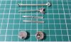
So, continuing with the valve gear, the expansion link requires two holes to be drilled in the castings before assembly. This is not mentioned in the instructions, but phographic evidence and the Beattie drawing shows them to be there. I marked the position for drilling the holes using the drawing as a guide.
20180801_085121.jpg

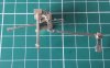
And after fitting to the radius rod. This needs to slide freely in the expansion link so ensure there are no burrs left from drilling the holes . Below are the valve rod and slide bars. The upper bars are tabbed together and the tabs removed with the piercing saw after fitting.
20180731_213357.jpg

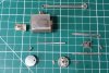
Here's the valve rod guide after assembly with the slide bar and rod inserted.
20180731_213316.jpg

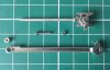
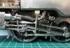
Next, the expansion link brackets ready for fitting to the slide bar bracket.
20180731_213250.jpg

And after fitting with the expansion link and radius rod. Also an upper view of the valve rod guide slide bars, showing the read cast holes for the oil pipe.
20180731_213225.jpg

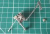
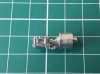
Here the eccentric rod has been joined to the expansion link with 0.8 mm NS rod, and to the return crank with the cast pivot supplied. It has been soldered at rear and then dressed flush. Below is the cast brass bearing cover.
20180731_213151.jpg

And after fitting the cover. This has three lugs which locate in the holes in the bearing face of the return crank. I soldered it with the minimum of solder at these three location only, to avoid the risk of excess solder seeping inside and impairing the rotation.
20180731_213110.jpg

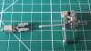
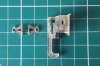
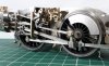
Here is the cross head and piston after soldering, along with the connecting rod, brass bearing, 12 BA screw and castellated 12 BA nut. Again, this latter hand made item is far from perfect, but will pass muster from normal viewing distances. I'm surprised that MOK don't supply castings for these items, which I'm sure with their pattern making capabilities would be far better than I could make. In this view I have also added the "cork" to the little end of the connecting rod. The rod was cut shorter after this shot was taken.
20180731_213037.jpg

The system won't let me add the remaining images I wanted to use, despite being below the maximum 15, so I will continue separately.
Cheers,
Peter
 

Attachments

  • 20180731_213151.jpg
    20180731_213151.jpg
    179.9 KB · Views: 36
  • 20180731_213225.jpg
    20180731_213225.jpg
    162.6 KB · Views: 31
  • 20180731_213037.jpg
    20180731_213037.jpg
    166.1 KB · Views: 34
  • 20180731_213110.jpg
    20180731_213110.jpg
    156 KB · Views: 31
  • 20180731_213316.jpg
    20180731_213316.jpg
    132 KB · Views: 30
  • 20180731_213250.jpg
    20180731_213250.jpg
    161.9 KB · Views: 34
  • 20180731_212440.jpg
    20180731_212440.jpg
    251.2 KB · Views: 42

P A D

Western Thunderer
Here's the con rod attached to the cross head. 20180731_213008.jpg

And the left hand valve gear completed except for the lifting links. The union link and combination lever have been pinned using 0.8 mm NS rod. There's a little more cleaning up to do but I'm pleased to report, it all runs smoothly.
20180731_212832.jpg

Here's a view from above. Not much to spare between cross head and crank pin, but enough.20180731_212401.jpg

And my usual gratuitous finale.20180731_212757.jpg


20180731_212440.jpg

I'm getting there, but Warren Haywood has just dropped me a line to say my Duchess will be finished some time soon, so I may be distracted re assembling that.

Cheers,
Peter
 

Attachments

  • 20180731_212440.jpg
    20180731_212440.jpg
    251.2 KB · Views: 25
  • 20180731_212757.jpg
    20180731_212757.jpg
    229.2 KB · Views: 26

P A D

Western Thunderer
Ken - would it be fair to say that S7 is a little more demanding than having a 'floating' middle axle? BTW chaps, thanks to both for documenting the details. They form a super supplement to the manufacturers instruction books!
Dave

Hi Dave,
I'm glad you have found the build interesting and thanks to you for your input which I have found useful.

Not wishing to open a can of worms here, but could more demanding mean more troublesome? :)

Only joking.

With regard to a simple floating middle axle vs the more elegant engineering solutions, whether it be csb, compensation, sprung horn blocks or whatever, surely the only way to prove the merits of one system over the other, whether running on "narrow"or "broad" gauge, would be to make a direct comparison using two identical models of the same weight, with the same motor/gearbox, running on well laid vs poorly laid track work? It may be that one system is better than the other, depending on the quality of the track work, but if any body has ever done that I'm not aware of it and until some body can show me evidence of that sort, for me the jury will always be out.

Not withstanding the above, it may be that with scale seven, some form of compensation or springing is beneficial, but for finescale, with my own experience, I'm not convinced. That said, unless I have problems with the compensated rear axle on the 4MT, I will give it a go. I can at least compare the running against the DJB one that my brother owns, which has a fixed rear and beam compensated middle and front axles, albeit that if has a Slaters gearbox and motor and mine will have an ABC Maxon.

Cheers,
Peter
 

Dikitriki

Flying Squad
Hi Peter,

Can you adjust the angle of the slidebar support bracket? To my eye, it seems to be at too rakish an angle.

I would echo what Daifly said. Threads such as these are a superb adjunct to the instructions, and a great advert for the kit.

Richard
 

Dikitriki

Flying Squad
Actually Dave, I don't think that's right either:) I know it's JLTRT, but that seems too upright compared to a lot of other photos I've seen. I wonder if that's the camera angle.

Richard
 
Top