Phil's GW coach bodging

Phil O

Western Thunderer
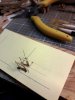
Well I was hoping to report that I now had a rolling coach, but after several disasters I still don't. I have tried soldering them up as designed, but I couldn't find a way to hold it all square with the wheels in and a soldering iron as well. I had some etched brass bogies to which cosmetic sides could be added, the brass bits were easy, but attaching the cosmetic sides has resulted in melted sides. I pre tinned both parts with low melt solder and I hoped that putting the iron on the brass etch would get it hot enough to run the solder using a 40 watt iron, this wouldn't get the parts hot enough to run the solder, so I flashed up the 60 watter and it melted the the white metal. There has been a lot of very blue language. I will now order some more bogies and glue them, unless anyone has some suggestions.

Thanks to those adding likes.
 

LarryG

Western Thunderer
Soldering whitemetal bogie sideframes to brass innards :- Like you, I use a 40 iron and normal solder (not low-melt), brush on the liquid flux, carry a small blob of solder to the 'join' and apply the iron to the brass adjacent to the whitemetal casting. The solder runs onto the whitemetal and I remove the iron immediately. Job done. A tacking job each end is all that is necessary (shown in red near arrow). Capillary-like action takes the fluid solder wherever the flux is. (Soldering whitemetal to whitemetal is a different story with a different solder).
WEB Bogie & solder..jpg
 

Phil O

Western Thunderer
Thanks Larry,

I was trying to solder along the full length, when the new sides arrive I will have another go.

Thanks.
 

Phil O

Western Thunderer
Larry

Thanks very much for your advice, I was going the whole hog, rather than just taking the sides to the frame.

Cheers.
 

Phil O

Western Thunderer
A bit more progress has been made despite trying to cut the skin off my thumb the other day which has left it sore, when I touch the afflicted are with something.

Anyway the bogies have been made up, except the whitemetal castings, which should be with me soon, I hope.

Auto 41.jpg

And yes I did fold the one on the left the wrong way hence some solder on the outside of the bends to reinforce them.

The queen post casting are too wide to fit between the solebars and have to be cut in half and reduced a bit too fit.

Auto 42.jpg

The 2nd the is spaced off the first using the truss bars.

Auto 43.jpg

And finally all in place.

Auto 44.jpg

That's all for now.
 

Phil O

Western Thunderer
The replacement bogie castings have arrived, so that I will be able to get the bogies done.

The underframe is progressing, the trussing is complete and the V hangers and brake cylinders added. I now have to decide on the gas cylinders, whether too use cast white metal or fabricate them from brass or plastic.

Pictures of progress will follow when I can download the photos from the phone.
 

Phil O

Western Thunderer
The other truss bars were fitted and thoughts turned to the steps.

What follows is how I am doing it after a couple of false starts.

I placed the Dartcastings angle template on a block of wood and drilled a hole, using this hole as a datum. I then cut one of the supports from the fret and located it on the template, with the holes aligned over the line on the template and cut a piece of brass wire and stuck it through the hole, I the drilled the other two holes and fitted a length of wire through each. I the removed the template and using a couple of set squares to draw parallel lines through each of the holes.

Auto 53.jpg

The template was the put back on the block of the wood with the bits of wire as a guide and the support was fitted and soldered to the wires.

Auto 54.jpg

The solder was cleaned up. Using the step etches, I placed them in position over the template, one end going over the wire to position it. The bottom step hole was aligned over my pencil line and drilled through and a piece of wire through the etch into the hole.

Auto 55.jpg


Using the other step support and the step with the free end they were aligned with each other and over the appropriate pencil mark and a hole drilled. Sorry about the quality, but holding the pin vice and phone was a bit of a juggling act.

Auto 57.jpg

Another piece of wire cut and fitted.

Auto 58.jpg

The steps were removed and the support replaced and soldered to the wires.

Auto 58a.jpg


I will break now as I have run out of time. Please wait for the next thrilling instalment of making Auto coach steps!!
 

Attachments

  • Auto 59.jpg
    Auto 59.jpg
    201.9 KB · Views: 1

Phil O

Western Thunderer
OK, to puck up where I left off yesterday. The steps threaded on.

Auto 59.jpg

and the other uprights,

Auto 60.jpg

Starting too look the part now! removed from the jigm

Auto 61.jpg

And finally the completed steps, I have left the fixing bracket loose, to aid fitting to the body.

Auto 62.jpg

This morning. I finished doing the others and got up to make a cuppa and inadvertently knocked one off the bench, I hadn't realised this until I went too muster them all for a group photo. I found it on the floor, you guessed it I had trodden on it, the air was quite blue for a while, apologies if I have offended anyone with my out burst.

Edit:- Please see post 3 on page 3, before proceeding further!
 
Last edited:

Phil O

Western Thunderer
I wish that I could report that I had sorted the steps, but I have had several attempts at rebuilding the set that I damaged last week, so far to no avail.
 

Phil O

Western Thunderer
Finally got there after much swearing and cursing.

Auto 63.jpg

The next job will be to fit the steps to the solebars and then add these little blighter's to the floor and the step. I will then solder the lot up so;id, before tiding it all up.

Onwards and upwards! hopefully!!
 

Phil O

Western Thunderer
some progress has been made, the steps at the driving end are fitted/

Auto 64.jpg

Looks rough and ready at this magnification.

It's now starting to look the part.

Auto 65.jpg

and then another snag,

Auto 66.jpg

The bogie fouls the steps at this end, I now have to decide the best way forward. My current options as I see it is to try and dismantle the bogie pivot and move it back by a couple of millimetres, but as the bit that the bogie rides on is a big chunk of whitemetal which may not take to be warmed enough to remove it.

Auto 46.jpg

Or to take a piece out of the inner step upright and hope it doesn't show too much, as this is the inner gangwayed end, or a third option that so far I've not thought of.

Auto 67.jpg

Any advice would be welcome.
 

Phil O

Western Thunderer
Whilst making an emergency visit to my parents, I have had time to ponder the options and when I return home, I'm going to cut the inner uprights as if necessary I can fabricate new ones, whereas if I turn the whitemetal into a molten blob, I don't have the means to recast it, well not without finding something to make a mould.
 

LarryG

Western Thunderer
Larry,

Thanks, if I can remove the bogie castings, I will give it a go.

I would nip it off with with Xuron tinsnips and solder it further back. If you wreck it, use a piece of brass from the scrap box. Flux the joint and hold the soldering iron on the new cross-member close to the join to protect the whitemetal sideframe from excessive heat. As soon as the solder has run from the cross-member onto the sideframe, remove the iron. Hope I'm not preaching here. Just trying to assist.
 

Phil O

Western Thunderer
Thanks Larry,

This is the first time that I bodged at this level, so it's a bit of a learning curve, hence some of the mistakes, but I am determined to get the blighter sorted. Any tips and assistance is all gratefully received and sometimes you can't see the wood for the trees and a fresh approach or pair of eyes can make all the difference.
 

Phil O

Western Thunderer
Back now from y parents, at least for the moment!

Thanks to Larry's suggestion, well nearly! I have built another bogie, but with one transom cut off and reversed

Auto 68.jpg

the transom was offered up and soldered in place with the wheels in situ, the wheels were then removed and I attacked the reversed transom with a grinder to roughly get the correct shape and the gradually fettled to get enough swing

Auto 69.jpg

Once happy the bogie was finished off as the previous ones, with the whitemetal sides.

Auto 71.jpg

Auto 72.jpg

Now that it looks good on it's wheels, I will clean up the steps and make a start on the auto gear at least on the leading driving end and then make a decision on how much additional gear to fit; this being a layout vehicle rather than a show case jobby!

Thanks Larry for the advice, it worked a treat.
 

LarryG

Western Thunderer
Glad it is turning out. This was a coach I fancied, but going O gauge has put all former construction ideas on hold for the time being. There is something about the older GWR auto trailers.
 

Nick Rogers

Western Thunderer
I've really enjoyed reading through your thread Phil; I have a David Geen diagram P kit to do eventually. As Larry said, I do like the older GWR auto trailers.

Looking forward to future posts!

Kind regards,
Nick.
 
Top