Simple loco to fill a space!

Ian@StEnochs

Western Thunderer
I have been a WT member for a while now and have enjoyed the many and varied threads, contributed a little, learned a lot of useful tricks and picked up some new techniques. Over Christmas I have been building a little simple loco to fill in the time between painting my last project, slow job, and starting the next one, and of course in between the celebrations. As you do just before the Bells I was thinking over things and realised that perhaps a we thread on a simple scratch build might be of interest.

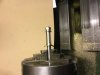
The loco in question is a 'Fower Wheeler'. Designed by James Stirling for the G&SWR way back in 1871. These engines had a long life with some lasting until 1920 mostly on coal workings where there short wheelbase let them go where larger engines could not. Until recently there was very little information on these engines available with only one photograph and a frames plan. When I changed over to 7mm my 2nd loco was built based on the info then available.


image.jpeg


However recently another photo has been found which has increased our knowledge and given me the urge to build another.

image.jpeg

Photo courtesy Glasgow & South Western Association.

This picture shows the engine circa 1906 and just right for my modelling period. With the previously available info And the picture I think I can make a reasonable likeness.

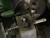
Work started on Christmas Eve and moved quickly, I didn't take pictures until this afternoon when I started this thread but here is where I am at.image.jpeg
Frames and coupling rods. As this is a simple slow moving engine I have opted for 3 point compensation rather than full springing. The front axle runs in a tube pivoted at its centre and guided at the ends with square wire horn cheeks and a box. The plunger pickup tubes are fitted and will be invisible when painted. The plungers will be lengths of brass wire.
image.jpeg

I will be fitting a representation of the motion to fill in the space between the frames but it will be non working.

More later,

Ian.
 

Attachments

  • image.jpeg
    image.jpeg
    122.9 KB · Views: 23

Ian@StEnochs

Western Thunderer
Here are the wheels and ashpan in place. The wheels are Slaters, 5'2" turned down to 5' to give the thin rim appearance of the original. I have also thinned them down to 3.25 thick tyres and recessed the spokes on the back. Tyre profiled with S7 form tool and 31.2 back to back gauge.
image.jpeg
The rods are just on for show. The motor is a Mashima TA12 from stock and drive is via 40-1 worm to a lay shaft and 3-2 spur drive to the axle. This engine is never going to be a fast runner.

image.jpeg
Footplate, buffer plank brass and valances from milled section.
image.jpeg
Boiler and cab. I made this on Wednesday as I had a whole day while missus was at the sales. The riveting took a bit of time but effective. The smoke box is a separate assembly with the brass joining ring sandwiched between it and the boiler and held with a nut and bolt. The smoke box has a large slug of lead encased inside for weight. As yet the boiler is empty. The hole in the cab front is for fixing to the firebox.
image.jpeg
Just placed to see how it looks so far, a wee bit down at the rear but that is an optical illusion. Next job splashers but ready to party now.

Ian.
 

ceejaydee

Western Thunderer
I'll enjoy watching this loco take shape as your prototype is very similar to the NBR Wheatley Y10 that I've always fancied building a model of.

Superb platework :thumbs:
 

Ian@StEnochs

Western Thunderer
Hi All,

This morning I got the splashers made and fitted. As I have a lathe I use it when possible so the fronts are turned up with the beading and a rebate for the tops. Bit of 28thou Nickel silver, kit waste in this case, is cut roughly to shape with tin snips and soldered on to a bit of brass tube.
image.jpeg
This is then turned down to the outside diameter and the front recessed to leave the beading. With NS I use some Rocal cutting fluid and power feed from the centre out. The recess is about 15 thou deep.
image.jpeg
image.jpeg
I hope you can see what is happening, lathe stopped for photos! The rebate on the back is turned with a parting tool, this time hand fed 10 thou deep for the splashers top.
image.jpeg image.jpeg
The fronts are now marked and segments sawn off with the piercing saw. You can get 3 fronts from each disc, just right for an 0-6-0 but a couple of spares left with this loco.
image.jpeg
You can see one sides components, the tops are sheared 10thou strip rolled in my boiler rollers and the other disc is 10thou for the backs. I will cut it after fitting as illustrated in the next picture.
image.jpeg
This shows one splashers finished and the second partly assembled. You will see that I have soldered the top into the rebate and then this assembly onto the back. The bottom of the beading is filed back, the oversize back makes holding easy, for the piece of brass angle to be soldered on. The fronts are rubbed flat with a piece of wet and dry paper on a board. The extra backing is snipped off with tin snips and filed flush on the bottom.
image.jpeg
Splashers soldered onto the footplate.

No more workshop time today. Tomorrow I hope to get the boiler and cab assembly fixed and perhaps a bit more.

Simon, I will explain my pickups later as I have run out of plungers and I like to make a batch at the same time.

Ian.
 

Steve Cook

Flying Squad
Lovely clean work there Ian :)
Fascinating to see a lathe being used to turn sheet materials, I guess thats a whole different ball game to the bar-stock I've not graduated from yet.
Can I ask, when you use the parting tool to create the recess on the top of the splasher, it looks like you have ground it with a V profile on the cutting edge - is this to force the tool to cut on two faces and thus stop the thin material being deflected fore or aft of the tool?
A nifty trick if so, I'll do my best to remember that one!
Steve
 

Ian@StEnochs

Western Thunderer
Can I ask, when you use the parting tool to create the recess on the top of the splasher, it looks like you have ground it with a V profile on the cutting edge - is this to force the tool to cut on two faces and thus stop the thin material being deflected fore or aft of the tool?
Steve

Thanks Steve,

The parting tool is ground square on the end and fed straight in. It has about 5 degrees top rake and only cuts on the front. I agree though both the photos appear to show a vee but that is a trick of the light.

Ian.
 

Ian@StEnochs

Western Thunderer
Well I didn't get the cab and boiler fixed because I took the notion just to continue with the lathe work and get the chimney and safety valve casing made. So here goes, sorry about the photo quality, it's not very easy taking pictures on the lathe without glare and lots of background clutter.
1st job is to make a rough sketch with basic dimensions. I usually take a copy of a modellers drawing and add sizes from the GA. However there is no GA for this loco so I am using my experience and sizes from similar locos. Figures converted to mm.
image.jpeg
The stock bar needs to have the saddle fly cut. I used to do this in the lathe but since I got a coordinate table for the pedestal drill I just do it there. The stock is 19mm free cutting brass. The fly cutter is a piece of 12mm steel bar cross drilled for a broken 6mm milling cutter with a drilled and tapped hole in from the end for an allan screw to lock it in place. The broken cutter is ground to a round end with no rake. Run at about 400rpm and the spindle moved by hand. Feed about 0.2 mm until the saddle is formed.
image.jpeg
The blank is now mounted in the lathe and faced off to length and a hole drilled right through for a mandrel, 7mm in this case, while there I counter bore the base 12mm with an end mill, for the mandrel to fit against.
image.jpeg
Next job is to rough out with a parting tool using the sketch for sizes.
image.jpeg
You can see I forgot to take the photo at the right time and had started taking some metal off the flare! However now it's the creative bit and using a round nose tool ground to a radius suitable for the job. A bit of manipulating the tool with both feedscrews, gets easier with practice, to generate the shape. Keep comparing with a photo if you have them to get the correct shape. I run the lathe at top speed for this bit, 2100 on the Myford.
image.jpeg
image.jpeg
This is how far I can go just using the lathe tools. Next job is forming the skirt. For this I rough form the skirt on a tool I made after seeing it described somewhere in the model press but I cannot remember where. It saves a lot of time and makes a difficult task a lot easier.
image.jpeg
This shows most of it. The blank, still on the mandrel, is mounted into the block and the hand wheel with spring, bottom right, fitted at lathe centre height. The blank can be turned against the ball ended cutter mounted in the chuck. The clever bit is that there is a little pin beneath the saddle on the blank which makes the cutter follow the curve of the saddle as the blank is turned.
image.jpeg
You can see the pin to the left of the chimney here. Run the cutter at top speed and take very fine cuts as you manually rotate the blank clockwise against the rotation of the cutter. Choose a ball ended cutter to match the required curves on your prototype. The cutter forms the skirt but it will still need some work with files to blend all the curves.
image.jpeg
Use files to blend all the curves. Use the biggest files you can. I have found that those sold for sharpening chain saws are excellent and come in a range of diameters. I find it easier to use a parallel round file than the tapered rat tail type?
image.jpeg
It helps to turn the chuck by hand back and forwards as you file. Finish with finer files and wet and dry paper.
image.jpeg
The finished chimney, you can see I have drilled holes for the bolts in the base. I usually chemically blacken the brass before soldering the chimney to the smoke box.
The safety valve base is a bit easier to make than a chimney. It is blind drilled from the base, tapped 4BA and held on a screwed mandrel. It still needs drilling for the valves and spring but that is for another session.

I have made quite a bit of progress over the last week but we are back to porridge and old clothes tomorrow so there won't be much time for modelling.

Ian.
 

Attachments

  • image.jpeg
    image.jpeg
    179.9 KB · Views: 31
  • image.jpeg
    image.jpeg
    158 KB · Views: 26

Overseer

Western Thunderer
Ian,

Looking very nice, I am itching to get the lathe and sheet metal out again. A device like your chimney skirt cutting setup was described by Paul Berntsen in MRJ years ago when he was doing a workshop series. I have never made one as I was not convinced by his results but you have shown it is how you use it rather than the device itself. The problem I saw with the original examples was the ball nose tool was used all round at the same setting to form the finished shape so the radius ended up too sharp on the longer sides, instead of using it to remove bulk material before finishing with files as you do.
 

Ian@StEnochs

Western Thunderer
Ian,

Looking very nice, I am itching to get the lathe and sheet metal out again. A device like your chimney skirt cutting setup was described by Paul Berntsen in MRJ years ago when he was doing a workshop series. I have never made one as I was not convinced by his results but you have shown it is how you use it rather than the device itself. The problem I saw with the original examples was the ball nose tool was used all round at the same setting to form the finished shape so the radius ended up too sharp on the longer sides, instead of using it to remove bulk material before finishing with files as you do.

I remember now thanks.
Before I made the tool I struggled with rotary burrs and files Which worked ok but took a lot of time. Also controlling a burr in a rotary tool is not the easiest job, I have had my share of ruined blanks when the burr took control.
Making the tool did not take very long and it has had a lot of use. However like all tools it takes a bit of practice to get the best from it.

Ian.
 

Ian@StEnochs

Western Thunderer
Hi all, Simon asked about the pickups.

I got a bit of time today so got the working bits of the pickup plungers fabricated. I had already fitted the guides when I made the frames. You can see them here.
image.jpeg
Basically it is a piece of brass tube with a sleeve of plastic and another brass tube inside that. I drill the frames to suit and fit a piece of tube through both and solder firmly in place. A cutting disc makes short work of removing the centre leaving about 5mm each side. A bit of Plastruct tube is then cut slightly longer and glued in, Araldite usually, and a bit of smaller tube goes inside that. I leave all slightly proud of the outside of the frames and dress them off flush when the glue is set. Under a coat of paint the only bit you see is the hole!

The pickup itself is a piece of straight wire, in my case 30 thou brass, I have used nickel silver and copper but brass works best for me. The wire should be a free sliding fit in the guide tube and of course aligned with the centre of the back of the tyre.

image.jpeg

This picture shows the parts and one in position. The wire is passed through a hole and soldered to a strip of 10 thou NS with another hole further along for the wire. The end which rubs on the tyre should be filed off square and polished on fine wet or dry. Fine flexible wire is soldered to the end of the strip and provision has to be made at the design stage for the wire to get back to the motor.

The clever bit is the 'Toilet roll holder' which pushes the plungers apart and against the wheels. I make mine from the bit of tube I cut off earlier with one end closed off with a cap with a hole in the middle. The plunger is a bit of the Plastruct tube rubbed down to be a sliding fit and adjusted to length such that it can be sprung between the plungers. The tails need to be trimmed so that the holes each end locate and that the spring is slightly depressed but not too much. The spring in the picture is there to illustrate the principal, I use the springs from Slaters horn blocks which are quite light. A bit of fine tuning on your model can be done by filing a wee bit off the end of the plastic.

On this loco there is no side play on the axles but this design permits the wheel set to move from side to side with no loss of contact presure as the pickups move with the wheels. The fine wire used is virtually invisible and can be made more so by chemical blacking the plunger with only the end left bright.

Oh one other thing, you need to remember that the plunger is only held by the pickups. If you need to remove them remember or you could loose the spring as it jumps for freedom. Been there, more than once!

Ian.
 

Scale7JB

Western Thunderer
Damn, just put Slaters pickups in two J68's and yours would have been a better option...

Next time.. Thanks for the 'how-to' though..

JB.
 
Top