The A5

Steph Dale

Western Thunderer
Martin,

I recall that my 4mm version had the cut outs for the bogie frames extending the whole way up through the frame.

The bogie mounting and buffer beam reinforcement were body - mounted I think.

Struggling a bit, it was probably 20-25 years ago...

Steph
 

Martin Shaw

Western Thunderer
Thanks for your thoughts Steph, I am constrained by what JPL have supplied me, their catalogue shows differing bogie frames with lower inner top edges, if that makes sense. I think they have given me the wrong type. We'll see.

Regards
Martin
 

Martin Shaw

Western Thunderer
Letters have been sent, the postman will undoubtedly bring news in due course. A couple of afternoons of faffing about have sorted out the chassis. Initially I dismantled it to measure the wheelbase, a difference left to right of 0.1mm wasn't the cause of the problem, and whilst the axles don't seem to be at 90deg to the frame they are all off in the same direction. This is I think due to differential expansion and contraction when soldering the frame spacers and wheel bearings in place. When you dealing with material this thick a torch is all but essential IMO. Anyway I discounted this as the source of the problem which really left the side rods. Dimensionally they measured the same but there were definitely tight spots on the crankpins. Following time immemorial practice I eased the running clearance on the crankpins, and no I didn't file oval holes, until it could be pushed along the bench without binding.

Todays exercise involved installing a motor, I had already bought a MSC helical set up for it, however it looked a bit weedy to drag the GC lump around so I substituted a JH. Connect the power and away we go, well it did but, it sounded like a bag of spanners. The gear set was grinding better than a miller, and the rest didn't sound good either. Aah I thought probably needs oil, which it did because after lubrication it all quietened down and once the gears had run for a bit and polished the rag off it was sweet.

Much cheered by this I put the chassis in the body, the crankpins now clear the balance pipes, but something else is catching deep inside. What wasn't immediately obvious to me, but should have been, is that everything is now a bit further out. A go with the mini drill should sort it.

No pics cos there's nothing new to see really.

Regards
Martin
 

Martin Shaw

Western Thunderer
The supplier of the drill set has offered a full refund, so they have been returned, unfortunately my alternative supplier is out of stock, b****r. The postman brought me an envelope today with replacement bogie frames, which looked good. Unfortunately I still have an issue with the bogie lifting the driving wheelsets upwards, double b****r. I wondered whether there may be an issue with the diameter of the bogie wheels, Mr Sharman gives a dimension of 3' 6", 24.5mm scale, the actual wheels measure 24.75mm at the root of the tread so they're pretty much spot on. I don't know what isn't right, I don't have a drawing to examine, but since I bought what purported to be a chassis kit for an A5 I shouldn't need one.

The one bright thing today was the delivery of a collet chuck and a set of ER25 collets, as well as an index head, so the milling machine can earn it's living. The plan is to take off 1.5mm from the main frames between the bogie wheels, which will allow the front end to sit on the bogie pivot spring, instead of the bogie frames. I have also decided that the bogie pivot is a bit too sloppy in the frame spacer, so I'm going to make one that fits. I'm up for a bit of self flagellation apparently. This was supposed to be any easy fix.

Yours Aye
Martin
 
Last edited:

Martin Shaw

Western Thunderer
Yesterday I was supposed to be driving 60009, unfortunately it failed at York on Friday, with what we hear is a broken piston, or at least badly damaged rings. Either way it wasn't going to end up in Scotland on Saturday so West Coast Railways sent a Black 5 from the Fort to Bo'ness to cover the Edinburgh - Inverness working today. So I got to have a play with 45212 instead, there's only one thing better than a Black 5, and that's two of them. Other railways inferior offerings are available. When I commented to the stoker that the K1 was going to be added at Perth, his laconic reply was," just another thing for us to tow about".

Back to business. I started making the new bogie pivot, here we see the turned pin about to have it's square end milled.
IMG_0229.JPG
In truth the collet chuck is uncomfortably close to the index head, a taper collet would be better. Note to self. The original is lying on the table. It all went quite sweetly and I ended up with something useful that fitted.

The frames have been adjusted,
IMG_0230.JPG
and when it's all put together, some joy,
IMG_0233.JPG

all the wheels are on the deck and the main frames now don't rest on the bogie frames, it's looking good. Not only that since the pivot is now a close fit in the frame spacer, the shoogleosity is at a minimum. Quite a productive afternoon really.

Regards
Martin
 
Last edited:

Martin Shaw

Western Thunderer
Some of you really observant people will have realised from my last post that the bogie pivot pin sits proud of the main frame top edge, why is this a problem I hear you ask? During the fiddling about this afternoon a trial assembly proved that when the engine tried to sit level the top of the pin retaining screw was reaching the underside of the smokebox before all the wheels reached ground zero. This was sorted, despite the bogie having been soldered together, in a somewhat contentious engineering exercise, proper engineers look away now,
IMG_0236.JPG
anyway, 3.5mm was skimmed off which seemed to do the trick. The front fixing screw, 8BA, decided it was big headed so I reduced this which seemed to make the front end happy. At the moment there is a major weight imbalance, a lot of lead in the bunker, but none anywhere else, which allows the bogie spring to slightly lift the front drivers, so that's the next thing to sort out.
At last after far too much faffing and not a lot of planning on my part the frame and bogie and wheels fit into the body, Nothings knocking due to the application of a large file internally, and it's staring to go somewhere positive. I know that frankly it doesn't look all that different from my picture of the 2nd February, but heyho. BTW the crankpins have had a facing, which improved them no end.
IMG_0237.JPG


Enjoy the council elections tomorrow.
Regards
Martin
 

Attachments

  • IMG_0236.JPG
    IMG_0236.JPG
    308.6 KB · Views: 1

Rob Pulham

Western Thunderer
Enjoy the council elections tomorrow.

Ordinarily I would be in the thick of them, - I coordinate and manage all the IT support for our elections. But we have a fallow year for local elections this year so would have had nothing at all if the General hadn't been called next month.
 

Martin Shaw

Western Thunderer
Having looked at the chassis in position and thought about it a bit, I wonder whether the frame cutouts for the bogie wheels should be bigger, enough to clear the flange at least, any thoughts good folk? I started looking at pick ups on Saturday, I was going to try Dikitriki's neat arrangement, but there really is insufficient room betwixt wheel rear and frame to get it all in, so that's on hold whilst my attempt at thinking goes on.

Yesterday I had a driving turn, so it was a bit of an early start, but a glorious day weatherwise, much to gladden the heart. Austerity tanks, for some bizarre reason, are somewhat derided in preservation, possibly by there ubiqiuety, but get them into the big valve and the noise brings joy, Beethoven didn't do any better, I had a great day.

Whilst fixing the side gate today the spanner and said gate came into close contact, my thumb being the preventative, some sweary words ensued and the digit has gone Joseph on me.

I retired hurt to the workshop where I made the prototype axlebox,
IMG_0251.JPG
IMG_0249.JPG
Sorry the pics are a bit out of focus, I must read the camera manual for this close up stuff. It's turned out not too bad, although pretty obviously the axle hole is off centre, most likely because I did the machining operations in the wrong order, at least I think that's what's wrong. For what I intended to be an 8mm square it's finished dimensions are 8.05 by 8.21, the latters a bit much but I can live with .05mm error. More thinking and practice needed, but it's a start. I know this isn't actually anything to do with the A5, but this is a convenient place for it pending a thread in due course for a new project which it will be part of.

Regards
Martin

P.S Marginally better quality pictures have been substituted this morning.
 
Last edited:

Martin Shaw

Western Thunderer
In my last post I posed a question, which in hindsight was a bit naive, and had I thought, could easily have been answered myself by consulting Mr Yeadon. Having done so it's obvious that the bogie wheel cutouts in the frame are woefully undersized and will need mechanical attention. Oh deep joy, something to think about later as I have to do my locomotive driver competency exam today, no doubt Monsieur Walschearts waggly bits will have to be explained amongst other things.

Regards
Martin
 

Martin Shaw

Western Thunderer
Well I passed my exam, so that's me for another two years.

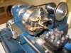
Steph in post #61 planted a thought which I have now followed up, my last post recognised the problem, how to fix it though. I realised a rotary table was needed if I didn't want to completely dismantle the assembled frames. I most certainly didn't, and whilst I had planned to get one in due course, circumstances accelerated the purchase which arrived on Friday. Machine tool bling.
IMG_0254.JPG
I can be quite as shallow as anyone else and therefore seduced by shiny things, absolutely gorgeous.

I also had to determine the size of the existing cutout in the frames and workout how to mount it to enlarge the arc. Initially I struggled and then had a brainwave so I took the dimensions of the cutout, plotted them in CAD which told me the radius of the arc. It came out at 11.91mm, which is a ludicrous size to choose and undoubtedly down to my measuring, I think 12mm was the likely figure.

Mounting the table on the mill required a centre, the hole in the middle above is 24mm dia, and then I had another brainwave, that's the quota for the year used, if I made the table centre over length it could also be used as a fence to mount the frames which would automatically locate the centres in all the right places. Quite good huh.

IMG_0255.JPG

A 1" bit of brass being reduced to 24mm. This is pretty much the limit for the Cowells lathe, the chucks wide open and the top speed is rather two slow at 880rpm, 1200 would be better, however it and I managed, and with the addition of a 10mm spigot screwed into one end can be fitted into both a chuck and a collet as needed.
The table was located on the mill bed and the frames positioned for the first cut.
IMG_0257.JPG
IMG_0259.JPG

The methodology should hopefully be obvious, and with a holding of breath, no going back.
IMG_0261.JPG
The first cut was made. It seemed to work so I took the cutout to 2mm from the top edge which I had previously worked out should clear the wheel flange by 1mm. I was right pleased, so I quickly put enough of it together to see how it looked, this is the result.
IMG_0262.JPG
the front wheel with clearance the remainder to do on Sunday. Well earned curry followed.

Having established how to do it the rest was an exercise in mounting the frames with the holding clamps out of the way of the cutter, which was by far the most time consuming part.
IMG_0264.JPG

IMG_0263.JPG

Having enlarged all the frame cutouts the front sections were a little bit lacking meat so I soldered two bits of angle inside the top edge to provide some support.

IMG_0267.JPG
So there we are, pretty much a full weekends work to solve a problem which I shouldn't have had to. That'll teach me, maybe.

Regards
Martin
 
Last edited:

Martin Shaw

Western Thunderer
Thank you Steph for your kind words. What I really don't understand is why a "chassis kit" purportedly for an A5 should require so much modification to accept the correct scale sized wheels. The body mounting alterations I can accept are needed to fit into an existing model, with the limitations that imposes, but this wholesale alteration to frame cutouts would I expect be beyond most "average" modellers, whatever that may mean, indeed probably beyond me until recently. It does rather highlight how superlative Mickoo's work with the B1 really is. I will be seeing Dave Brooks next month so I'll have a discussion with him about it.
Regards
Martin
 

Martin Shaw

Western Thunderer
Today I have mainly been casting. The imbalance of weight in the body requires some correction and I worked out that a slug of lead 2" long by 1.5" in dia would fit nicely. The soup tin from lunch was filled with a scrap length of waste pipe and wet builders sand tamped down around it. Withdrawing the pipe left a nice hollow to fill. Morrisons provided a stainless steel ladle for £3 into which went the lead removed from the body way back in February. When molten the slag was pushed off the surface and lead poured into the mould. There was some very fierce noises so I left it to cool. I'm sorry there aren't any pictures of this but I thought a ladle of molten lead deserved full concentration, but when the mould was turned out I found this,
IMG_0272.JPG
it wasn't quite what I planned, the molten metal had deformed the sand. It's next to useless for the loco but I did consider entering it for the Turner prize.
I had another go this time retaining the plastic pipe as a former,
IMG_0273.JPG
somewhat better, it's actually upside down in the picture, and as you can see the unsupported top section of the pipe deformed under heat. Nothing ventured I had a third go with the pipe fully enclosed by the sand and pleasingly it worked fine.
IMG_0274.JPG
Now I could put that in the loco body as it is and it would do, but I'm actually going to make one somewhat longer so I can slice it to maximum length. It has improved the balance no end bit it's still a bit rear heavy.
Regards
Martin
 

Ian@StEnochs

Western Thunderer
Today I have mainly been casting. The imbalance of weight in the body requires some correction and I worked out that a slug of lead 2" long by 1.5" in dia would fit nicely. The soup tin from lunch was filled with a scrap length of waste pipe and wet builders sand tamped down around it. Withdrawing the pipe left a nice hollow to fill. Morrisons provided a stainless steel ladle for £3 into which went the lead removed from the body way back in February. When molten the slag was pushed off the surface and lead poured into the mould. There was some very fierce noises so I left it to cool. I'm sorry there aren't any pictures of this but I thought a ladle of molten lead deserved full concentration, but when the mould was turned out I found this,
View attachment 66802
it wasn't quite what I planned, the molten metal had deformed the sand. It's next to useless for the loco but I did consider entering it for the Turner prize.
I had another go this time retaining the plastic pipe as a former,
View attachment 66803
somewhat better, it's actually upside down in the picture, and as you can see the unsupported top section of the pipe deformed under heat. Nothing ventured I had a third go with the pipe fully enclosed by the sand and pleasingly it worked fine.
View attachment 66804
Now I could put that in the loco body as it is and it would do, but I'm actually going to make one somewhat longer so I can slice it to maximum length. It has improved the balance no end bit it's still a bit rear heavy.
Regards
Martin

Martin,

I often cast scrap lead for weighting and have had some success using moulds made from balsa wood and card. It is relatively easy to make special shapes for awkward places like ashpans and tanks. For boilers a card tube, toilet roll inner etc, is less likely to collapse than plastic. Be careful if using damp sand as it can explode if it is too damp.

Ian.
 

Martin Shaw

Western Thunderer
Ian
Thanks for your thoughts. Your right molten lead and water are not good company, I also found out the hard way that lead and tin cans stick together, very well.

I have decided, contrary to my original thought, to go with plungers, so whilst they are obtained along with brake hangers and springs, plug for Pollokshaws O gauge show in 3 weeks time, the A5 is in temporary abeyance.

I had the opportunity last night to visit the West of Scotland Signalling Centre at Cowlairs, which is the Network Rail and Scotrail Control centre along with the signalbox that will eventually control the whole of western Scotland, well that's the plan. Interestingly and somewhat bizarrely the triangle of lines it sits in are controlled from Edinburgh, whoever said the railways make sense. Nonetheless it was most interesting and rare opportunity, I'm glad I took it, much i changed since my days on the railway.
Regards
Martin
 

Martin Shaw

Western Thunderer
Crikey, very nearly three months have elapsed. I took the loco to the Pollokshaws show and asked the guys running the test track to push it round, to see whether it stayed on the rails, which it did, however it did show up a shorting problem around the front bogie. I also ordered wheels for the D15 and got brake hangers for that engines tender and the A5, and some of Mr Slaters plunger pickups. After that I was somewhat diverted by other matters until last weekend when I made up a motor mounting, rather crude and probably over engineered, but you can't see it and it works. I also drilled holes for the pickups, the wheel rim for collection is only 1.5mm wide so I scribed around the wheel and measured 0.75mm by eye, drilled 3.8mm the pickup body is a nice interference fit into the frame. Last week I was under the weather so nothing got done until today, wiring and other bits and pieces.
IMG_0379.JPG
I suppose the pickups ought to be glued into the frames eventually, the idea is that the brake hangers will hide the external view. Anyway it all seemed to work so having made the front lead weight short enough to clear the motor I popped the top on and took it for a hurl on the test track.
IMG_0380.JPG
You'll have to take my word that it does actually move on its own, although it's not as quiet as I would wish, no doubt some brasso on the gears would lap them in. Well it does run on 2 rail electrics, but since I currently don't have any curves more testing will be needed before it gets a tryout at Bo'ness. I feel a curry coming on.

Regards
Martin
 

Martin Shaw

Western Thunderer
There is upthread a pic taken in about 1959, of my father and his sons at the RHDR, sadly he passed away today at the age of 93. One abiding memory is of him mixing and applying Araldite to Wills kits in furtherance of better models. Thanks Dad RIP.
Martin
 
Top