JimG
Western Thunderer
I got the Sculpfun S30 at the end of December but it has had to wait until this week before it got its enclosure built, mainly because my temporary building board was being used to build track for the N scale layout up till last weekend. An enclosure with some form of fume extraction is pretty well a necessity with a laser cutter used in the home. My previous Emblaser 1 could create quite a fug in the room if I had forgotten to turn the extractor fan on.
I had hoped to use the enclosure I had for the Emblaser, but it couldn't accommodate the Sculpfun, mainly through insufficient height. I had a dig around on the Internet and found a video on Youtube where the laser cutter owner had built an enclosure using hardboard pinned and glued to square wood stock. I liked the idea, but don't like hardboard. So I copied his idea and used 5mm ply screwed to square wood stock instead. And the carpentry is not in the Chimtonstoke league - more like Clydeside Rustic.
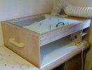
And here's the finished product. At the rear is the extractor fan which was used in the previous Emblaser enclosure, coupled up to a flexible hose which exhausts through the window. The base is a piece of 20mm covered chipboard from an unbuilt flat pack got some years ago but never used. It gives a good flat base which will help a lot when setting up the cutter and the metal honeycomb base. The case also has two large home-made handles, made when I found that the enclosure was quite a handful to lift and carry around.
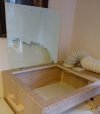
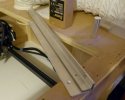
The lid is a piece of 3mm Perspex, got a good few years ago for another job, but never used. It was stored beside the fridge, but part of it got a fair bit of daylight, so part of the protective covering is well and truly stuck to the Perspex. This is a common problem but I have found that using Eucalyptus oil and a Plastikard scraper gets the stuff off without damaging the Perspex. And a bottle of Eucalyptus oil just arrived this afternoon so I can get onto cleaning it off quite soon.
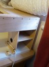
The Sculpfun S30 comes with a small compressor for the air assist facility. It is recommended that the compressor should be kept clear of any fumes, so the lower opening is to house it, with access for the tube to the laser head through the hole in the side with a home-made grommet using a bit of rubber tube slit lengthwise.
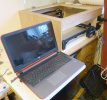
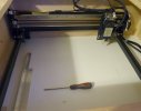
And here's the setup with the Sculpfun in place. The HP laptop in the foregound will control the machine.
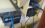
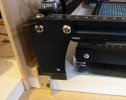
And a closer shot of the control box for the Sculpfun with the compressor lower right, and the power supply on the upper shelf. The power supply for the laptop will go beside the laser power supply and there is plenty of room to house a lot of the cabling along with the power supplies. The compressor has a six foot cable connection to the Sculpfun even though it has to sit cheek by jowl with it because of the air tube to the laser head.
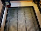
I've not finalised how I secure the Sculpfun in the case, along with the metal honeycomb cutting base I've also got. I've done a bit of double sided cutting and etching in the past and this needs good X/Y location when turning the material over to work on the second side. I worked out a way on the Emblaser but that took a bit of experimentation until I got success so I suspect I will need a bit of experimentation with this setup to achieve the same.
I've had a quick play around and have been able to move the laser head around and switch the compressor on and off using the Lightburn software on the laptop, so all is well so far. I'll get some bits of MDF under the laser tomorrow and try some cutting.
Jim.
I had hoped to use the enclosure I had for the Emblaser, but it couldn't accommodate the Sculpfun, mainly through insufficient height. I had a dig around on the Internet and found a video on Youtube where the laser cutter owner had built an enclosure using hardboard pinned and glued to square wood stock. I liked the idea, but don't like hardboard. So I copied his idea and used 5mm ply screwed to square wood stock instead. And the carpentry is not in the Chimtonstoke league - more like Clydeside Rustic.


And here's the finished product. At the rear is the extractor fan which was used in the previous Emblaser enclosure, coupled up to a flexible hose which exhausts through the window. The base is a piece of 20mm covered chipboard from an unbuilt flat pack got some years ago but never used. It gives a good flat base which will help a lot when setting up the cutter and the metal honeycomb base. The case also has two large home-made handles, made when I found that the enclosure was quite a handful to lift and carry around.


The lid is a piece of 3mm Perspex, got a good few years ago for another job, but never used. It was stored beside the fridge, but part of it got a fair bit of daylight, so part of the protective covering is well and truly stuck to the Perspex. This is a common problem but I have found that using Eucalyptus oil and a Plastikard scraper gets the stuff off without damaging the Perspex. And a bottle of Eucalyptus oil just arrived this afternoon so I can get onto cleaning it off quite soon.


The Sculpfun S30 comes with a small compressor for the air assist facility. It is recommended that the compressor should be kept clear of any fumes, so the lower opening is to house it, with access for the tube to the laser head through the hole in the side with a home-made grommet using a bit of rubber tube slit lengthwise.

And here's the setup with the Sculpfun in place. The HP laptop in the foregound will control the machine.

And a closer shot of the control box for the Sculpfun with the compressor lower right, and the power supply on the upper shelf. The power supply for the laptop will go beside the laser power supply and there is plenty of room to house a lot of the cabling along with the power supplies. The compressor has a six foot cable connection to the Sculpfun even though it has to sit cheek by jowl with it because of the air tube to the laser head.
I've not finalised how I secure the Sculpfun in the case, along with the metal honeycomb cutting base I've also got. I've done a bit of double sided cutting and etching in the past and this needs good X/Y location when turning the material over to work on the second side. I worked out a way on the Emblaser but that took a bit of experimentation until I got success so I suspect I will need a bit of experimentation with this setup to achieve the same.
I've had a quick play around and have been able to move the laser head around and switch the compressor on and off using the Lightburn software on the laptop, so all is well so far. I'll get some bits of MDF under the laser tomorrow and try some cutting.
Jim.

