Rob Pulham
Western Thunderer
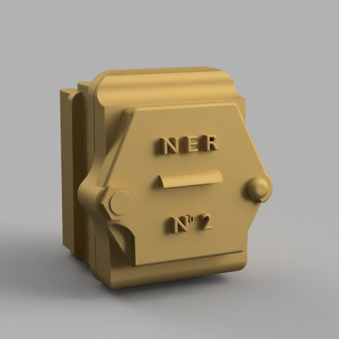
Funny you should say that Ian, an NER axlebox is possibly going to be attempted soon.


Rob
I am amazed at what you can do with 3d printing. Incredible!
Ian


They look just the ticketAlthough kind friends with printers have printed these in resin for me I really wanted to see what they would look like in brass so I asked Mike Hopkins if he would add some to his next batch going to the casters.
Should they be of any interest to anyone, Mike had some extras cast and they are £10 per set plus £4 P&P


I’ve been trying to get to grips with Fusion 360 for about a year now, but having used TurboCAD for my 2D and 3D drawings for many years, I’m finding the learning curve extremely steep!
I’ve lost count of the number of Fusion tutorials I’ve watched via YouTube and am really impressed with the software’s capabilities and the ease with which people (who know what they’re doing!), design stuff. It looks so much easier and faster, than using TurboCAD and I really must keep practising, gain some basic competency, then apply this to my chosen projects*.
Ian MacCormac did an interesting tutorial on designing and printing a loco chimney a year or so ago, via the Gauge O Guild. This was fascinating to watch and I followed the various stages and achieved the required end result. More recently, Chris Walsh has done some tutorials (again, via the GoG), the most recent one, being the above mentioned Zoom meeting a couple of days ago. As I don’t do Zoom, I’ll watch this, when goes on general release in the next few days. (Both Ian and Chris were kind enough to answer some questions I’d sent them via PM, so huge thanks to them both).
*I do have something to show for my dabblings with Fusion so far though. For Christmas, I received an Elegoo Mars 2 Pro 3D printer and an Elegoo “Wash & Cure”. (Believe it or not, I only opened the boxes about 3 weeks ago!). Anyway, having set things up, I successfully printed the “Rook” test pieces that are pre-loaded onto the Elegoo’s flash drive….
View attachment 144946
(They were very firmly attached to the build plate and I couldn’t get them off with the supplied scraper, hence damage to the right hand one - I had to resort to whacking them with a piece of 2” x 1” timber in the end!).
Impressed that a), the quality was really good and b), I’d managed to get my printer working 1st time, I remembered that I’d used Fusion, to draw a water scoop deflector dome, for the tender on my MOK Ivatt 2-6-0. The lost-wax casting supplied with the kit was OK, but the pictures in the instructions, showed a flare at the base of the dome, which was absent from the casting, so I thought I’d see if I could do it as a 3D print. This was (for me), a fairly simple excercise in Fusion and this is how it turned out….
View attachment 144938
The flare is visible at the bottom, but I added some sacrificial material, to protect it from potential damage, when removing the print from the build plate. This can be seen via Fusion’s sectional analysis feature….
View attachment 144939
(Mmmm, reminds me of a Jameson’s “Raspberry Ruffle”!).
I was well chuffed with the end result and after cleaning, drying and removing the support structure, the sacrificial material was removed, by swirling the dome around on some abrasive paper….
View attachment 144940
View attachment 144943
View attachment 144944
View attachment 144945
(I’m pretty sure threads are possible in Fusion 360, so I may well print another dome and incorporate a thread in the centre portion, thus enabling me to screw it to the tender from below).
Having shown this to a friend on Friday, he reckons I should print a new water filler too. As that particular casting is already Araldited on, I think I might pass on that!
Regards
Dan
The tender dome looks good but you could probably get away without using supports to print it. I try and avoid as much as possible using supports on my prints if I can. I find them a pain and they can damage the item they are attached to when removing them. With the tender dome all you need to do is say add a filleted edge at the bottom of the dome. If say you go for .5mm you design the dome to be .5mm higher than it should be. Getting the dome off the build plate will be made easier because you have a filleted edge where the bottom of the dome meets the build plate. Any damage done to the fillet won't matter because once of the build plate and cured you will sand away the fillet giving you the correct hight of the dome. For small items I use an artist palette knife, the thinnest you can get and providing you lay the knife flat on the build plate you won't scratch it.I’ve been trying to get to grips with Fusion 360 for about a year now, but having used TurboCAD for my 2D and 3D drawings for many years, I’m finding the learning curve extremely steep!
I’ve lost count of the number of Fusion tutorials I’ve watched via YouTube and am really impressed with the software’s capabilities and the ease with which people (who know what they’re doing!), design stuff. It looks so much easier and faster, than using TurboCAD and I really must keep practising, gain some basic competency, then apply this to my chosen projects*.
Ian MacCormac did an interesting tutorial on designing and printing a loco chimney a year or so ago, via the Gauge O Guild. This was fascinating to watch and I followed the various stages and achieved the required end result. More recently, Chris Walsh has done some tutorials (again, via the GoG), the most recent one, being the above mentioned Zoom meeting a couple of days ago. As I don’t do Zoom, I’ll watch this, when goes on general release in the next few days. (Both Ian and Chris were kind enough to answer some questions I’d sent them via PM, so huge thanks to them both).
*I do have something to show for my dabblings with Fusion so far though. For Christmas, I received an Elegoo Mars 2 Pro 3D printer and an Elegoo “Wash & Cure”. (Believe it or not, I only opened the boxes about 3 weeks ago!). Anyway, having set things up, I successfully printed the “Rook” test pieces that are pre-loaded onto the Elegoo’s flash drive….
View attachment 144946
(They were very firmly attached to the build plate and I couldn’t get them off with the supplied scraper, hence damage to the right hand one - I had to resort to whacking them with a piece of 2” x 1” timber in the end!).
Impressed that a), the quality was really good and b), I’d managed to get my printer working 1st time, I remembered that I’d used Fusion, to draw a water scoop deflector dome, for the tender on my MOK Ivatt 2-6-0. The lost-wax casting supplied with the kit was OK, but the pictures in the instructions, showed a flare at the base of the dome, which was absent from the casting, so I thought I’d see if I could do it as a 3D print. This was (for me), a fairly simple excercise in Fusion and this is how it turned out….
View attachment 144938
The flare is visible at the bottom, but I added some sacrificial material, to protect it from potential damage, when removing the print from the build plate. This can be seen via Fusion’s sectional analysis feature….
View attachment 144939
(Mmmm, reminds me of a Jameson’s “Raspberry Ruffle”!).
I was well chuffed with the end result and after cleaning, drying and removing the support structure, the sacrificial material was removed, by swirling the dome around on some abrasive paper….
View attachment 144940
View attachment 144943
View attachment 144944
View attachment 144945
(I’m pretty sure threads are possible in Fusion 360, so I may well print another dome and incorporate a thread in the centre portion, thus enabling me to screw it to the tender from below).
Having shown this to a friend on Friday, he reckons I should print a new water filler too. As that particular casting is already Araldited on, I think I might pass on that!
Regards
Dan


Sorry Mark, I missed this when you posted it back in January. I love it. You may have seen elsewhere that I did a few modifications to it to make it more rigid but it's does everything that I want from it now.Hi Rob,
What is your impression of your new lathe?
Mark


)")