Ian@StEnochs
Western Thunderer
Rather than clog up the workbench thread I’ve started my own, really prompted by Gareth’s work on his broad gauge Buffalo and his crank axle problem.
My latest project is a pair of Victorian 4-4-0s which with their small diameter boilers make the valve gear very visible. The valves are on top of the cylinders operated by rocking shafts and one also sports outside cylinders with the valve rod and rocker above the footplate. I did consider making the valve gear dummy but being a bit of a masochist decided that all would work!
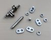
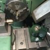
The most trying part of the job is making a crank axle, well 2 in this case! The photo shows one axle assembled and silver soldered while the component parts for the other are alongside. The parts were all made with the use of my trust Myford lathe.

To make the crank cheeks I shaped a piece of 16mm steel bar by milling and filing. The picture also shows the filing buttons which made filing the curves easier. It was then set up in the four jaw chuck and drilled 3/16” for the axle and 4mm for the crank pin.
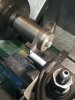
 Slices were then sawn off with a slitting saw in the chuck and the bar held in the tool post. A rub on fine emery paper removed any cutting marks and the holes were slightly countersunk each side for a solder fillet.

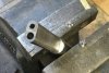
The crank pins were little turnings of rod held in a collet and turned to be push fits in their holes. These are assembled and lightly riveted to the crank cheeks, the shoulder ensuring the cheeks are held the correct distance apart.
The eccentrics are slices of 9/32 bar, 7.15mm, an odd size turned from 8mm steel but I have a 9/32 reamer which will do fine for when I make the eccentric sheaves. The rod was drilled 3/16” while held in the 4 jaw chuck and 2mm thick slices sawn off.
The axle is from Slaters and the centre of it has been slightly knurled with the edge of a file to ensure the parts stay where they should. Before assembly everything was dipped in thinners to remove any grease and all the holes had a shallow groove filed inside, with the edge of a 3 corner file, just to ensure the solder will penetrate.
Once all the parts were assembled and in the correct alignment silver solder paste was smeared around the axle between the cheeks and on the outside of the crank pins. The whole assembly was propped up on a little stand on a fire brick and heated slowly until the solder flashed. After cooling the black oxides we’re removed in a jar of ‘Picklean’ from Cookson gold, I think it is their version of citric acid. The solder paste ‘Brazepaste’ was from them too.
This is the first time I have Silver Soldered a crank axle. Previous ones have been pinned and soft soldered with 188 solder and Bakers fluid flux. Non have failed in service and one has been running for 25+ years now.
Next job will be to make the rest of the motion. I may be a while!
Ian.
My latest project is a pair of Victorian 4-4-0s which with their small diameter boilers make the valve gear very visible. The valves are on top of the cylinders operated by rocking shafts and one also sports outside cylinders with the valve rod and rocker above the footplate. I did consider making the valve gear dummy but being a bit of a masochist decided that all would work!
The most trying part of the job is making a crank axle, well 2 in this case! The photo shows one axle assembled and silver soldered while the component parts for the other are alongside. The parts were all made with the use of my trust Myford lathe.
To make the crank cheeks I shaped a piece of 16mm steel bar by milling and filing. The picture also shows the filing buttons which made filing the curves easier. It was then set up in the four jaw chuck and drilled 3/16” for the axle and 4mm for the crank pin.
Slices were then sawn off with a slitting saw in the chuck and the bar held in the tool post. A rub on fine emery paper removed any cutting marks and the holes were slightly countersunk each side for a solder fillet. The crank pins were little turnings of rod held in a collet and turned to be push fits in their holes. These are assembled and lightly riveted to the crank cheeks, the shoulder ensuring the cheeks are held the correct distance apart.
The eccentrics are slices of 9/32 bar, 7.15mm, an odd size turned from 8mm steel but I have a 9/32 reamer which will do fine for when I make the eccentric sheaves. The rod was drilled 3/16” while held in the 4 jaw chuck and 2mm thick slices sawn off.
The axle is from Slaters and the centre of it has been slightly knurled with the edge of a file to ensure the parts stay where they should. Before assembly everything was dipped in thinners to remove any grease and all the holes had a shallow groove filed inside, with the edge of a 3 corner file, just to ensure the solder will penetrate.
Once all the parts were assembled and in the correct alignment silver solder paste was smeared around the axle between the cheeks and on the outside of the crank pins. The whole assembly was propped up on a little stand on a fire brick and heated slowly until the solder flashed. After cooling the black oxides we’re removed in a jar of ‘Picklean’ from Cookson gold, I think it is their version of citric acid. The solder paste ‘Brazepaste’ was from them too.
This is the first time I have Silver Soldered a crank axle. Previous ones have been pinned and soft soldered with 188 solder and Bakers fluid flux. Non have failed in service and one has been running for 25+ years now.
Next job will be to make the rest of the motion. I may be a while!
Ian.


")

