7mm Bromwick: late-green/early-blue diesel layout

pricei

Western Thunderer
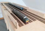
I finally started to lay some track - this is the section from the fiddle yard traverser to the station throat. I did deliberate for some time over what material to use as underlay. In the past, I've always used cork but I was interested to read about the foam that other forum members have tried recently. In the end, I stuck with what I knew - I prefer to pin or screw my track down and was concerned the foam might have got compressed resulting in uneven track. In addition, as my locos are now DCC sound-equipped, noise probably won't be as much of an issue as it has been on previous layouts. I am going to try the Mapei latex solution that SimonD suggested for ballasting, though, rather than diluted PVA.

In case anyone's interested, the lineside cable troughs are the ones that Phil at Intentio laser cut for me. Some of the frets include parts to allow hollow troughs to be constructed so their lids can be left off or skewed as you often see on the prototype. The troughs obviously need to be painted and, once ballasting and landscaping have been completed, I'm guessing you may only see the lids anyway.

Ian

PXL_20210414_121331801.jpg
 

Yorkshire Dave

Western Thunderer
Some of the frets include parts to allow hollow troughs to be constructed so their lids can be left off or skewed as you often see on the prototype. The troughs obviously need to be painted and, once ballasting and landscaping have been completed, I'm guessing you may only see the lids anyway.

I've often seen single sections of the trough left on the ballast (rather than taken away) where they have been renewed.
 

pricei

Western Thunderer
I've often seen single sections of the trough left on the ballast (rather than taken away) where they have been renewed.

Now you mention it, I do recall seeing a few discarded sections too. I'll certainly have a few troughs and lids leftover so I'll try that once the ballasting is done. Thanks.
Ian
 

pricei

Western Thunderer
One of my objectives for wiring up Bromwick was to really try and avoid the need for any soldering underneath the baseboards. One option would have been suitcase connectors but I prefer to use these sparingly - I've found in the past they can be unforgiving if you make a mistake and the wiring can get a little untidy when you have to use several connectors close together.

What I decided to do was run a pair of 32/0.2 wires along the length of the layout to form the DCC bus. I then bought a quantity of PCB screw terminal blocks and soldered these to pieces of 64 x 25mm stripboard. The blocks come in 2- and 3-way versions and conveniently clip together in a row to provide the exact number of connections needed on each baseboard. The soldering can obviously be done in advance on the bench.

PXL_20210508_140718682.jpg

Each stripboard is fixed to the baseboard (with screws and 3mm plastic spacers) and its first terminal wired to the DCC bus using a suitcase connector. The remaining terminals (which are all electrically connected via the stripboard) can then be used for dropper wires or other components needing a DCC track signal such as accessory decoders or servo controllers.

So far, it's proved to be a remarkably cheap and flexible solution and I'm now using the same method for turnout frog wiring and 12v power distribution as well. In the photo below, the blocks on the right are connected to the red/black DCC bus wires and two of the remaining terminals are used for dropper wires. The unused terminals are for track yet to be laid.

PXL_20210504_132223893.jpg

For those that are interested, the terminal blocks on the left (in the photo above) are connected to an extension of the DCC bus used for block detection. The normal DCC track signal is fed to monitored track sections (blocks) via the orange wires and returns via the grey wires in the photo below to a detection module. As well as reporting when a block is occupied, the detector I'm using uses RailCom to identify the decoder address of any loco present in the block allowing you to keep track of where trains are on the layout. Many ESU, Lenz and Zimo decoders support RailCom.

PXL_20210504_131549346.jpg

My main reason for implementing block detection was to use it with JMRI software to automatically control the layout signalling. Because RailCom goes a step further (by reporting the location and speed of locos), it opens up some interesting possibilities which I'm looking to try out such as automatically starting and stopping the flange squeal function on sound decoders when a particular loco passes through, say, a double slip or sharp curve.

Ian
 

pricei

Western Thunderer
Track laying continues at Bromwick. I've always admired fellow modellers able to build their own track. I did have a go at making a point myself last year but it didn't go well and I quickly concluded that Peco bullhead would be a far more realistic option for the layout.

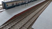
Apart from the goods sidings, all of the station trackwork is now in place. In the distance, you can hopefully see the framework for the first platform. A second will be located on the left along with station buildings and a footbridge linking the two platforms.

Trackwork.png

With the points and occupancy blocks now wired up and tested, I've been able to install some additional signals. One issue I only discovered recently was that the accessory decoders I'm using expect common anode wiring whilst my signals are common cathode. Fortunately, the mismatch was easily resolved with some small adapters. You can see these in the picture at the end of this post - they're the four small PCBs connected by yellow wires to the decoder.

Signals.png

I think I mentioned previously that I planned to use JMRI to control the signals. Although the software includes two different methods of configuring signal logic, I found them a little heavyweight for my requirements. So, I donned my software developer's cap and created a short script for each signal that sets the correct aspect whenever a dependent point or occupancy sensor changes its status. There's a screenshot of the control panel below. The software is currently running on a Windows laptop but once everything's finished, I'll be moving it over to a Raspberry Pi.

JMRI panel (Bromwick).PNG

On my last layout, I used Tortoise motors for switching points but I was keen to try out servos at Bromwick. Whilst they're certainly cheaper and more compact, I'm not convinced they sound as good as a proper slow-motion motor. I'm going to try experimenting with the servo speed to see if I can get them to sound a little more realistic.

The final photo shows a servo installed using a 3D-printed mount. The mounting holes needed a little enlargement but the plastic is easily filed and forms a rigid structure once screwed to the baseboard. The unit below the servo is an accessory decoder for controlling the servos and rather cleverly allows a DCC throttle to be used to accurately adjust the extent of the servo motion when switching point blades. It proved to be a useful feature given the throw on a Peco double-slip is quite a bit less than on their points. The four small PCBs attached to the decoder outputs are miniature relays used for changing frog polarity.

Wiring.jpg

Ian
 

pricei

Western Thunderer
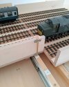
One of the jobs I've been putting off for a while was completing the trackwork and wiring on the final two sections of my fiddle yard traverser. The first section has worked fine but I'd always been a little anxious that the 'play' in the drawer runners might lead to track alignment problems on the middle section which is 1440mm long.

Fortunately, my fears were largely unfounded and, whilst there are a couple of traverser permutations where some of the tracks don't align precisely, it's not been enough to cause any problems or derailments. I suspect the weight of 7mm models and their low speed in the fiddle yard helps as well.

PXL_20220120_095903723.jpg

My initial plan for locking the traverser sections into position (after they've been moved) was to use small door bolts. I tried several different types but they all exhibited some slackness between the sliding barrel and its mounting plate - useful when closing a door but not really what you want with a traverser. After some thought, I decided to try making my own bolt using 3mm brass rod. This offered the desired snug fit inside 4mm tube which was then mounted to the front of each traverser section with small U-brackets.

The final part of the plan was to drill a series of 3mm holes into the wood battens supporting the runners for the bolt rods to drop into. Unfortunately, I found it impossible to achieve this with the desired accuracy and decided to try gluing small squares of thick plasticard (pre-drilled with 3mm holes) to the battens instead. Lowering a brass rod into a hole allowed the plasticard to be positioned precisely while the glue set. So far it's proved to work well and allows each traverser section to be easily locked into the desired position.

Ian

PXL_20220120_093904613.jpg
 

paulc

Western Thunderer
One of the jobs I've been putting off for a while was completing the trackwork and wiring on the final two sections of my fiddle yard traverser. The first section has worked fine but I'd always been a little anxious that the 'play' in the drawer runners might lead to track alignment problems on the middle section which is 1440mm long.

Fortunately, my fears were largely unfounded and, whilst there are a couple of traverser permutations where some of the tracks don't align precisely, it's not been enough to cause any problems or derailments. I suspect the weight of 7mm models and their low speed in the fiddle yard helps as well.

View attachment 155278

My initial plan for locking the traverser sections into position (after they've been moved) was to use small door bolts. I tried several different types but they all exhibited some slackness between the sliding barrel and its mounting plate - useful when closing a door but not really what you want with a traverser. After some thought, I decided to try making my own bolt using 3mm brass rod. This offered the desired snug fit inside 4mm tube which was then mounted to the front of each traverser section with small U-brackets.

The final part of the plan was to drill a series of 3mm holes into the wood battens supporting the runners for the bolt rods to drop into. Unfortunately, I found it impossible to achieve this with the desired accuracy and decided to try gluing small squares of thick plasticard (pre-drilled with 3mm holes) to the battens instead. Lowering a brass rod into a hole allowed the plasticard to be positioned precisely while the glue set. So far it's proved to work well and allows each traverser section to be easily locked into the desired position.

Ian

View attachment 155279
Hi Ian , you could have used the plasticard with the hole as a template . Locate , clamp & drill the wood , repeat etc but what you have done works and thats the important thing .
Cheers Paul
 

Dog Star

Western Thunderer
Work on the fiddle yard traverser is now underway. I'm probably being a tad ambitious but I thought I'd try making one that comprised three sections - a smaller one at each end capable of holding a diesel or coach and a longer, central section that's long enough to accommodate three coaches. The intention is to be able to run a loco around a rake of four Mk1 coaches within the confines of the fiddle yard area.
Just so I understand... how can a loco run around a four coach set when the central portion of the fiddle yard is long enough for no more than three coaches?
 

Neil

Western Thunderer
Just so I understand... how can a loco run around a four coach set when the central portion of the fiddle yard is long enough for no more than three coaches?

I think I've worked this one out. Loco draws train in, uncouples, slides across to a vacant road and runs back to the sliding section at the entry of the fiddle yard. Carriages hand shunted along into the space vacated by the loco. Loco slides across to what is now the head of the train, couples up and is ready to depart.
 
Last edited:

pricei

Western Thunderer
I think I've worked this one out. Loco draws train in, uncouples, slides acroos to a vacant road and runs back to the sliding section at the entry of the fiddle yard. Carriages hand shunted along into the space vacated by the loco. Loco slides across to what is now the head of the train, couples up and is ready to depart.
Spot on!
Ian
 

Barnaby

Western Thunderer
That's some excellent modelling you've achieved there Ian. It just goes to show take care of the detail and you will have an extraordinary enjoyable model railway to run and observe.

Best
 

pricei

Western Thunderer
That's some excellent modelling you've achieved there Ian. It just goes to show take care of the detail and you will have an extraordinary enjoyable model railway to run and observe.

Best
Thank you, Barnaby. I just wish I could devote more time to the layout and make faster progress! I should have a few new photos to post in a week or so.
Ian
 

Gismorail

Western Thunderer
Some superb work going on here and I'm very interested in your traverser build something that I want to put into operation when I build my forthcoming 0 gauge layout. I will be catering for six coach trains on a continuous run so I will watch with great interest on how you get on with the build.
Some nice flowing track work into the station area which proves that carefully laid Peco track does look good and if you take you time on the ballasting you will produce a very convincing look.
 

pricei

Western Thunderer
Thank you for the comments. You're absolutely right about the ballast. I've been trying out some different samples recently and been surprised at how overscale the chippings often are in ballast that's sold for O-gauge. I've had to resort to sieving to achieve a realistic looking size.
Ian
 

pricei

Western Thunderer
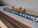
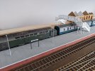
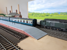
Work on the station at Bromwick is progressing with assembly and painting of the down/bay platform now pretty much complete. In the background, the carcass of the up platform is just visible behind the coaches along with the unpainted footbridge kit and part-assembled station buildings.

PXL_20220404_123939647-1.jpg

I managed to download a font similar to Rail Alphabet - that's the one used on BR signage from the mid-1960s - and used it to print the station names for the running-in boards and lamppost plates. They've come out fairly well but I have to say I was relieved to be working in O-gauge. The thought of having to cut, glue and assemble signs in a smaller scale wouldn't have held much appeal.

PXL_20220404_090204277-2.jpg

The lampposts include working LEDs but they're quite fragile and I decided it might be prudent to make the platforms removable to facilitate any repair or replacement necessary in the future. To ensure the platforms could be re-positioned accurately, I used some plywood offcuts left over from constructing the baseboards to form a series of locating lugs for the platform framework to fit around. The gaps between the lugs are to accommodate the wiring and resistors for the lighting.

PXL_20220403_110754123-3.jpg

The lampposts were supplied with cold white LEDs so I changed these to soft white versions to be more in keeping with the period of the layout. They're wired up in parallel with 1K resistors.
Ian

PXL_20220403_214659174-4.png
 

Barnaby

Western Thunderer
I've just been having an extended read through your build topic. Really been taken with your traverser workings, given me some ideas.

Best
 

pricei

Western Thunderer
I've just been having an extended read through your build topic. Really been taken with your traverser workings, given me some ideas.

Best
I will admit to being a little pensive when I embarked on construction of the traverser - my carpentry skills are limited at best. What made a difference - and it's probably the best advice I could offer - was buying good quality plywood cut square and to size from a woodyard. That left me with essentially just an assembly job using drill, screws and glue.
Ian
 

pricei

Western Thunderer
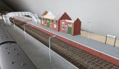
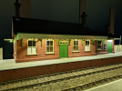
The second platform at Bromwick is now nearing completion and work on the station building is progressing well. I was looking to add internal lighting to the building but a quick test revealed a lot of light 'leakage' around the window frames and through small holes left over from the laser cutting process so I may have to abandon that idea and just rely on external lighting from the lamps over the doors and under the canopy. Incidentally, for any users of Vallejo Model Colour paints, the doors were sprayed with a 50:50 mix of Light Green (70.942) and Medium Olive (70.850) which I thought afforded a reasonable representation of Middle Chrome Green.

PXL_20220802_104054128.jpg

I'd previously printed the station names for the lampposts and running boards myself but it was a fiddly job and I decided it would be a lot easier to buy a pre-printed sheet for the remaining station signage and posters. When the sheet arrived, I was surprised at how big the signs actually were and realised the running boards I'd made - which I'd sized purely by eye from old photographs - should probably have been a fair bit larger. Something I'll try to rectify when I get the chance.

PXL_20220802_104200049.jpg

I've also started ballasting the up/down tracks through the station. After experimenting with a few different brands of O-gauge chippings, I ended up using a blend of light and dark grey and sieving out the larger pieces. I used neat IPA as a wetting agent followed by a 50:50 mix of water and latex solution as a fixative. Once dry, the sleepers received a quick dusting of weathering powders to provide a more random appearance. I'm not sure if the latex solution actually helps that much in reducing noise transmission but it certainly makes it easier to remove the ballast if you ever need to correct an error or change the track alignment in the future.

PXL_20220802_105849477.jpg

One curiosity I noticed with the latex was that it occasionally exhibited a tendency to creep up and pool on the top of the sleepers (see the photo below). Strangely, it only happened on the down track. After racking my brains for a while, I realised the only difference between the two was that I'd sprayed the down line with the enamel version of sleeper grime paint but used the acrylic version on the up track. I can only conclude that the enamel paint somehow induces a capillary action effect causing the latex solution to rise up. Fortunately, the problem was easily resolved by soaking up the excess fluid with a tissue before it dried.
Ian

PXL_20220715_110339562.jpg
 

pricei

Western Thunderer
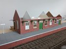
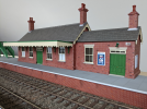
Aside from adding guttering and downpipes, the station building at Bromwick is now complete. After much experimentation, I went ahead and installed some lighting inside the waiting room only to find it was impossible to see it once the canopy lights were turned on! A lesson learned.

PXL_20221020_133720011 (1).png

Achieving a realistic look for the chimney flashing took a few attempts. First, I used leftover roof slates but they were far too thick. Next, I tried postcard offcuts painted grey but they still weren't really thin enough. I then looked on the internet and came across a downloadable sheet of pre-printed roof flashing (TX00b) from Scalescenes. Although they don't offer a 7mm version, the company did suggest printing the OO version at 176% scaling which worked fine - I think it captures the mottled appearance that lead acquires with exposure to the weather reasonably well.

PXL_20221104_145456205 (1).png

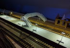
Here's a night shot of the station with the platform and building lights on. It also shows the platform fencing - made from an Intentio kit - just visible on the left and right of the picture.

PXL_20221104_165751103.png

I've also made a start on the backscenes. I needed around 7.5m of imagery for the scenic section of the layout so I chose one from the ID Backscenes range where scenes can be joined together. Having read mixed reviews of the paper version (which needs to be glued), I decided to try the self-adhesive option. The manufacturer recommends attaching the image to 3mm Foamex board so I ordered five lengths cut to size. The photo below shows the first image in place with the supports for the second board installed.
Ian

PXL_20221105_091706071c.png
 

simond

Western Thunderer
its looking rather nice, and thanks for the tip-off regarding flashing, I’ll look that out.

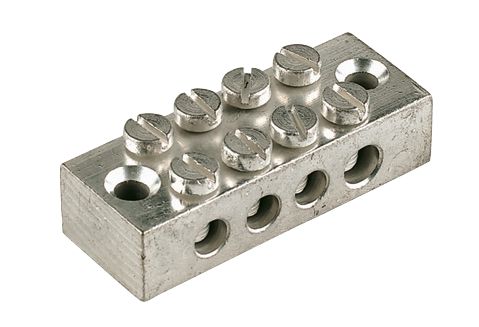
it’s a bit late now, but for busbar connectors, these are a good option.


worth shopping around as Screwfix used to do multipacks which were cheaper. 8-way ones also available. Maybe CEF or Toolstation.
 
Top