A SR Z Class loco - Nick Dunhill's Workbench

Nick Dunhill

Western Thunderer
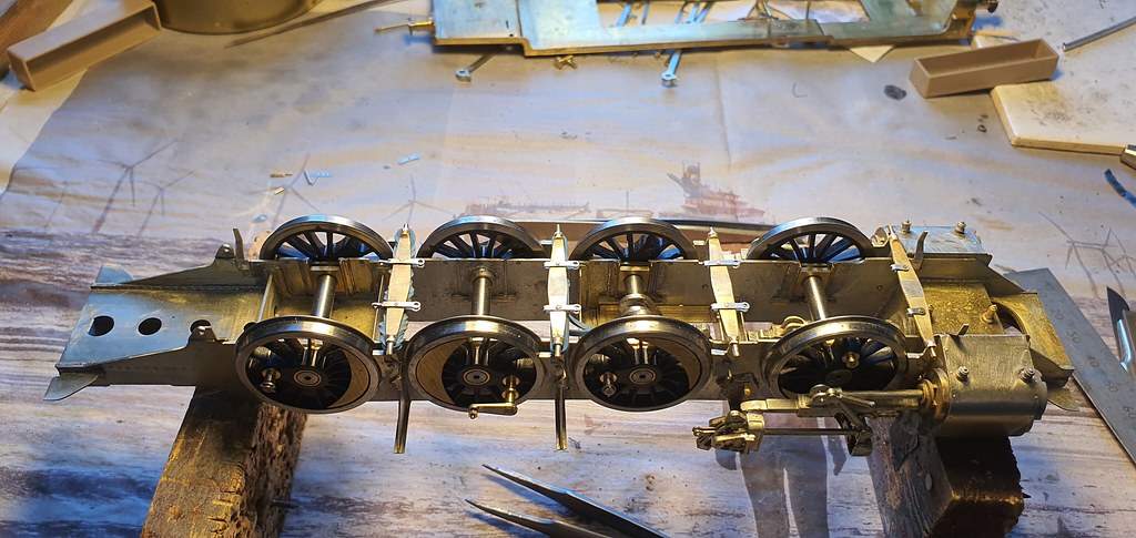
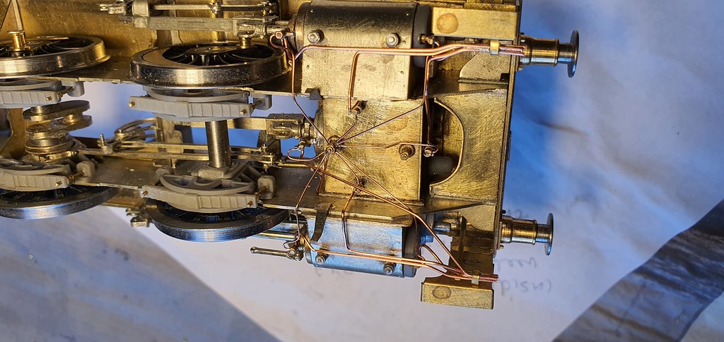
I have moved so far off piste with this build that I realised I would have to fabricate much of it myself. With this in mind I started to compare the drawings I have with the motion parts supplied by DMR. The main motion and valve rod brackets supplied are a very simplified version of the real thing. The expansion link is after the style of Gresley, a 3 bar arrangement with a bifurcated radius rod gripping the centre section. The kit isnt like this, and also the parts for the valve rod swing link don't really fulfil the correct movement. So it was out with the piercing saw! I made all 4 brackets and began laminating the etches supplied, modifying them as I went along.


51287310979_d831a34132_b.jpg


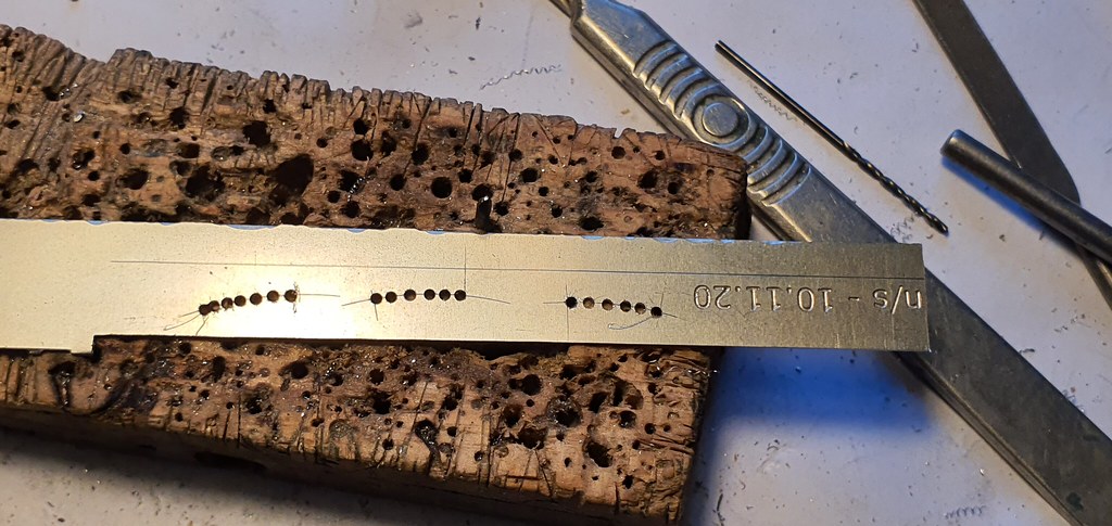
I began to get a bit exasperated at this point as the two halves of many of the rods did not match, and the hole centres didn't coincide. I had to solder them together and make good as best I could. The etches that fold up into the expansion link were particularly bad. They weren't the same length, the lightening holes were all over the place, the mounting holes weren't in the same plane and they were not symmetrical. I modified them, but in retrospect it would have been quicker to make new ones.


51287606945_24c61b81ac_b.jpg


51285843072_f9b5a07147_b.jpg


51285843172_c554baa165_b.jpg


The kit seems to have all the hallmarks of a 4 mm blow up. The simplified valve gear and brackets are probably ok in OO gauge but doesn't really cut it in 7 mm scale. Also all the errors will be exaggerated when enlarged. Anyway I managed to produce something that looks and functions as real loco.


51285831862_6aeec50828_b.jpg


51286750043_15bf5974b2_b.jpg


51286589881_3019d49fa2_b.jpg


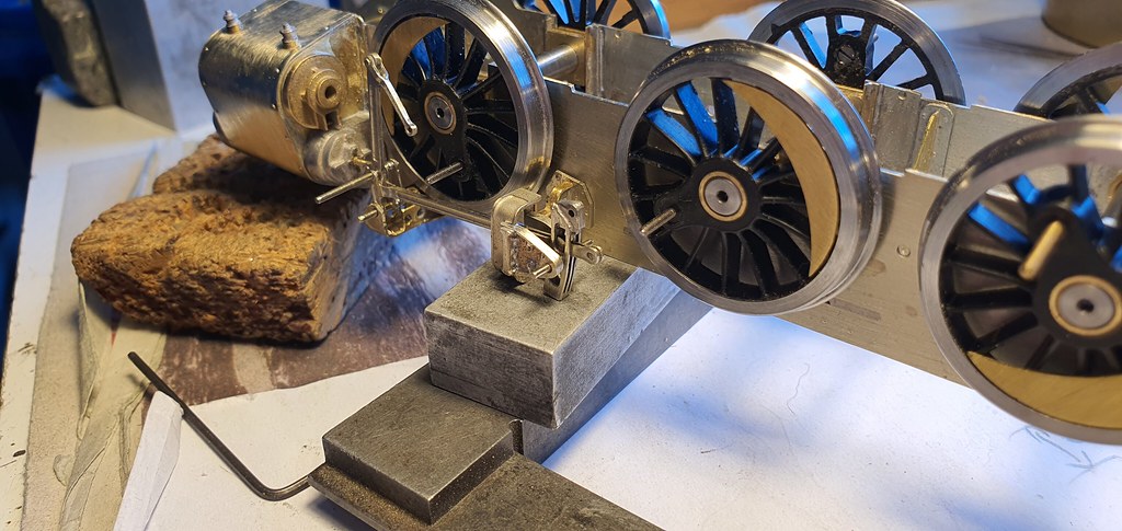
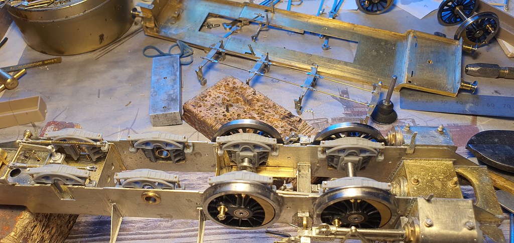
To fit up the motion I needed to fit up the slide bars and crossheads. I had seen on another thread how the etched slide bars provided don't fit the crossheads without a big reduction in size. I reached for some 1.6 mm square bar and gently eased the insides of the slidebar to accept it without loads of slop. I then checked some measurements on the GA and saw that the real slide bars are rectangular and not square. The crosshead also would put the slidebar far too high in the cylinder, ie it's far too tall. More parts to weigh in! I saw that Laurie Griffin has some alternatives in his range that look correct so I placed an order and moved on to the footplate while they turned up.


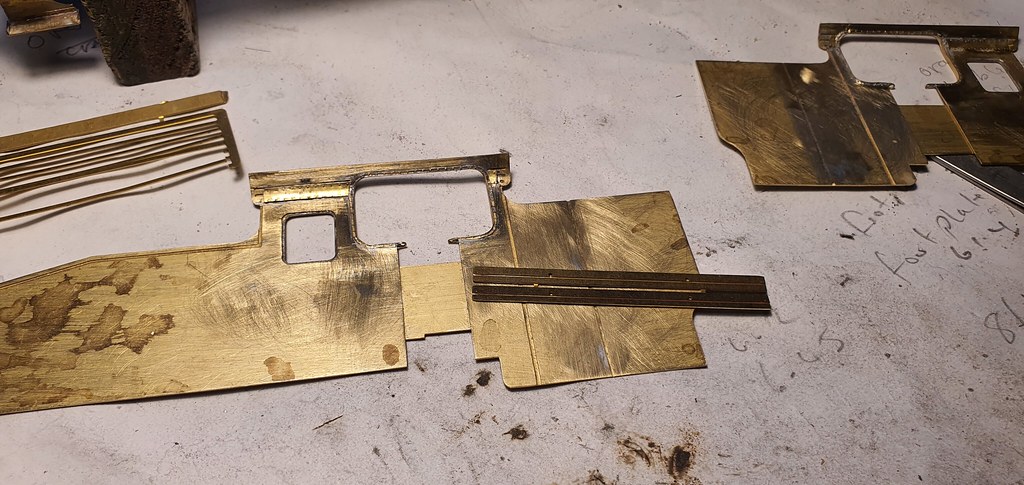
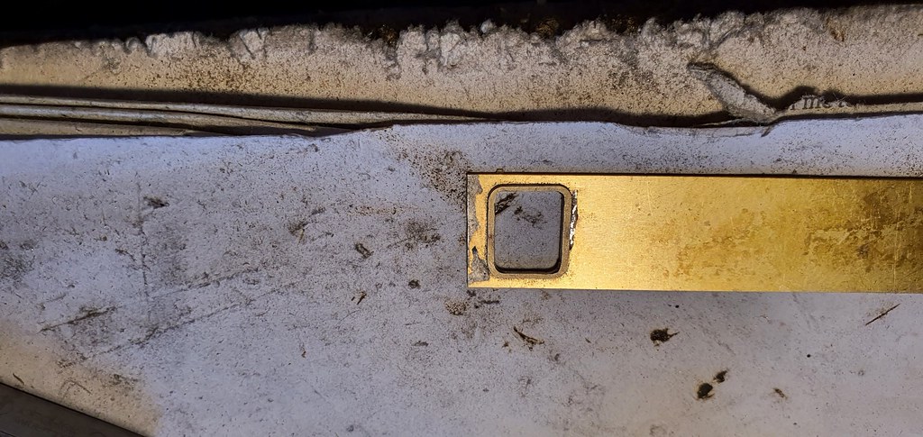
The footplate etch is a one piece affair with relief strips for forming the folds and curves. I began forming it and offering it up to the etched valance. I wasn't surprised to find that they didn't match! I fractured the footplate etch into 3 sections so I could tackle them separately. Also at this stage I offered the valance etch up to the chassis. If the completed footplate was going to land on top of the chassis at the rear and front, and hopefully in the middle, then the valance should be the same shape as the top of the chassis. It wasn't, by a mile! And the completed footplate would end up being too long by about 5 mm. This would also mean that the buffer beams would overhang the ends of the chassis by about 2.5 mm at each end. Also the completed footplate would need to sit on a beer mat placed above the cylinders to make it level.


51285892087_36e1270045_b.jpg


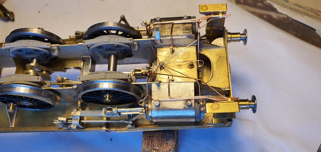
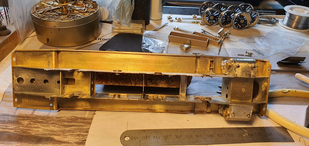
It took a day and a half to make a new footplate but it does now fit the chassis perfectly, and now meets the top of the chassis frames without the usual unsightly gap. I also made the bits of the chassis that stick up above the footplate. The valence is the original etch cut twice to fit. The lower platform, under the bunker, is as supplied as well.


51287311409_77791c661e_b.jpg


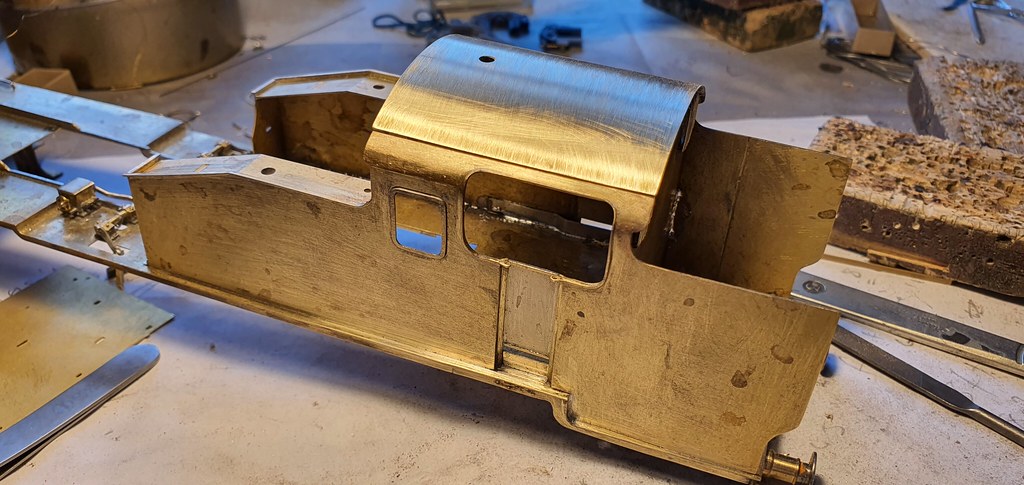
This pic shows all the cut out and formed parts taped to the chassis prior to tacking together.


51287596290_04e0b9c262_b.jpg


51286761413_ca6bfcb63e_b.jpg


51286590361_7a02a389d4_b.jpg


I'm glad all kits aren't as ill fitting as this, but I have to say that I have enjoyed all the fabrication.
 
Last edited:

chigley

Western Thunderer
just bought a ersa 80, after watching Nicks zoom recording, oh bugger now the washing machines gone bang literally.
Ken
 

simond

Western Thunderer
I’m on RDS80 mk3, the first two having been returned to RS, who have been excellent.

The wire, where it goes into the handle of the iron, seems to fail.

when it works, it’s the dog’s doobries.

Atb
Simon
 

chigley

Western Thunderer
I’m on RDS80 mk3, the first two having been returned to RS, who have been excellent.

The wire, where it goes into the handle of the iron, seems to fail.

when it works, it’s the dog’s doobries.

Atb
Simon
thanks for that Simon, not used it yet, busy sorting a new washing machine
Ken
 

Nick Dunhill

Western Thunderer
First job of last week was to modify the buffers so they became self contained. This would allow me to fit the gusset plates between the buffer beams and frames, the rear ones are quite visible. The buffers were easy to modify. I threaded the stem on the heads all the way along and cut them shorter. The boss on the rear of the stocks was cut back to match the thickness of the buffer beams and the hole in the rear of the stocks were partially drilled to allow a 12 BA nut to pass within.


51302055168_030e8af2cf_b.jpg


The corners of the stocks were drilled and fake fastners added.


51301119487_1937f895fa_b.jpg


51301864686_61386f7ca1_b.jpg


You can see that I fitted the destinctive SR 3 link screw couplers, and in actual fact the loco I am modelling has normal 3 link ones!


51301119862_8d3f298bc4_b.jpg


I ditched the cast crossheads and etched slide bars supplied in the kit as they were just wrong in every way possible (slide bars square and not rectangular, centres wrong, etc etc) but luckily Laurie Griffin sell some which are much better and fit nicely. I married them to the cylinder rear covers I had previously modified. The motion was then quite easy to fit up. A fair bit of bushing and shimming was needed to make it all work smoothly. I also had to recess the crankpin nut of the front wheel into the coupling rod boss. I thinned the boss to the necessary thickness and drilled part way into the journal to allow it to contain the nut.


51301120017_a6d1f2ef8e_b.jpg


51301120182_bab9ce844c_b.jpg


The eccentric rods supplied in the kit are too long (or more to the point are too long if you've built prototypically and not as designed) so I shortened them as required.


So here we are at the close of play on friday. Most of what you see has been scratchbuilt or heavily modified.


51302583864_cb9f9c82ca_b.jpg


51301865666_b8875d23b4_b.jpg


51301120477_ac7d0407fe_b.jpg


Inside motion next, but first a short break on the N Yorks coast! Happy days.
 

chigley

Western Thunderer
I’m on RDS80 mk3, the first two having been returned to RS, who have been excellent.

The wire, where it goes into the handle of the iron, seems to fail.

when it works, it’s the dog’s doobries.

Atb
Simon
rds80 works really well, once you sort the settings. still getting used to it
Ken
 

Nick Dunhill

Western Thunderer
After a lovely few days in the sunshine at Robin Hood's Bay it's back to the bench. First up was the connecting rod for the middle cylinder. I had an old con rod casting from LGM with a marine style big end. I modified that and mated it up with a rod made from the etches for the outside cylinder connecting rod, suitably shortened. Laurie Griffin sent me a crank casting that was pretty much identical to the one in the drawing.


51331606411_af661ec6e9_b.jpg


All the rest of the rods are scratchbuilt from scrap nickel siver strip. The expansion link parts were made alongside the ones for the outside motion and I scarfed some Laurie Griffin eccentric straps onto the eccentric rods. I used my own eccentric sheaves.


51331606571_3a1337cd33_b.jpg


51331818048_e10a8e9b5c_b.jpg


Next I had to make the 2 motion brackets, the drop links and a valve chest cover. Again all are made from scrap etch.


51331606916_da10c789f6_b.jpg


The whole lot was assembled into the chassis and the crank and sheaves soldered to the axle.


51332333689_6ffeaaf7af_b.jpg


The cylinder head, slide bar and crosshead are modified Laurie Griffin castings. Here it is running;


I then added the remaining frame stay, cut from scrap brass.


51332603740_ccd87f67a1_b.jpg


51330875552_f973a32e87_b.jpg


At close of play yesterday afternoon I had nearly installed the weigh shaft and lifting links, but not quite. You can see that I made the steam reversing cylinders too.


51332603815_f487308af4_b.jpg


You can see that I broke one of the lifting arms late on in the afternoon and called it a wrap at that point!

There are more pictures here; nick dunhill and if anyone knows what the mechanical lubricators provide a feed for on a Z I'd be grateful to know.
 

Nick Dunhill

Western Thunderer
A bit more progress this week, I finished off the lifting links for the motion. I also fettled the LGM Silvertown mechanical lubricator and added some feed pipes. I extended the drive lever so it would reach the outer eccentric rod (union link?) and obtain it's movement.


51349541598_f19cabccb0_b.jpg


51348325338_305668a356_b.jpg


51349331016_155304ef83_b.jpg


Not surprisingly the guard iron etches were waaay too short, so I made more.


51350348555_71d798d6fb_b.jpg


I also made the brake hanger/brackets/shoes and modified the spreader tie rods. and a few other parts. Because of the 4 mm origins of this kit the brake parts are very basic or non existant, so an upgrade is needed.


51349328731_5aabd2b999_b.jpg


I'll fit up the brake system next but after my holiday!


51350348740_04c6b8e83d_b.jpg
 

Nick Dunhill

Western Thunderer
I have now built up the brake system from a few of the kit brake hanger and block etches (as before the brake hangers are hand drawn and are all different sizes!) and a lot of scratchbuilding and repurposing of castings left over from other projects.

51392690069_29b6d240a8_b.jpg


There's a Heath-Robinson style handbrake operating arrangement on the brake shaft, and all of the rigging is detachable for ease of assembly and painting etc.

51392215143_d1f15ef421_b.jpg


51391195267_842c0b0605_b.jpg


Mick Davies printed me some axlebox/horn plates/keeper plates/springs and hangers. They're just cosmetic and designed to be glued around the brass horn cheeks after painting. The dummy axleboxes are just glued onto the brass structural bearings. They just add a nice touch of realism. I made a start fitting them up.

51392974675_0129a1f3a7_b.jpg


More next week.
 

Nick Dunhill

Western Thunderer
The fun continues. I added the rest of the printed horn guides etc last week. They are cosmetic items but really give the model a lift, thanks to Mick Davies.


51409156710_b169b33ed1_b.jpg


51408935674_b706a5dd72_b.jpg


Next up was the cylinder drain cocks. They're steam controlled, and once I had seen the pipe-and-rod view of all the pipework I decided to make it all, I just couldn't resist!


51407429127_298e92f601_b.jpg


51408935824_18eeee1873_b.jpg


Next I aimed my ERSA at the front buffer beam. I had to laugh at the etches for the lamp irons. Remember they're hand drawn, all different widths and sizes!


51407429142_a609eebd8f_b.jpg


I also made the sand pipes and pick ups. More of those later.....

More pics here nick dunhill
 

Nick Dunhill

Western Thunderer
This week I have completed the build from (and including) the footplate down. I added all the pipework for the vacuum and steam heat buffer connections.


51422154182_0163929a45_b.jpg


I'll have to revisit the vacuum brake upstand later when the bunker is installed and make it fit. I added all the angle that is unsually on a loco between the tops of the frames and the underside of the footplate.


Attention then moved to the upperworks. The etch for the cab/tank/bunker side actually fits. According to the drawing I have the bunker tapers in from about half way along. The kit is designed such that the bunker sides taper in fron the cab rear, but this isn't the case. I scored the back of the etch in the appropriate place to form a subtle bend in the bunker part way along. This was achieved by soldering a thick strip of waste etch to the bunker and running my slitting disc along it.


You can see the fold lines I produced here.


51422154702_a6e84c1b30_b.jpg


A closer look at the drawing revealed that the footplate tapers in towards the rear from a point in front of the cab opening. The kit is designed (and I built it so) to taper in from the rear step in the footplate. This will have to be altered but I decided to do it when the cab, tanks and bunker are installed to support the footplate when I remove the valence.


I spent the rest of the week detailing the cab sides and front and rear. I got very lucky and found some spectacle beading from a previous job that was exactly the same as the etched ones supplied. I wasn't so lucky with the rectangular side windows so made some beading using the etched ones supplied.


51423663974_00df7a31db_b.jpg


51422154447_f52ea0cd62_b.jpg


51423886420_6f5b7cd3b4_b.jpg


Now I have brass window frames for the inside as well as the outside of the cab.


The rear window frames had very crude protection bars etched in them. I didn't like that so cut them out and drilled the cab rear for the 12 vertical bars over each rear window. It took a while to fashon them from 0.5 mm rod!


The curve in the sides of the cab (that becomes the lower roof) was formed to match the front and rear. This was a tricky job, and to prevent the rest of the etch becoming distorted I soldered a wide strip of waste etch across the cab opening. The etch has some fold lines to help you along, but in reality you end up with a threepenny-bit shaped curve. I formed the curve, smoothed it to remove the folds and then formed the rivets. The plate join for the roof panel was also scored.

I added the 'reveals' for the cab doors, and the doors themselves (including hinges and latches,) and the upstands for the cab floor. The upstands also serve to hold the side etches straight while attaching them to the footplate. The beading round the cab openings were added. This was a tricky job as the bead has to match the curve of the roof.


51423160743_793187502f_b.jpg


Here are all the sections test fitted. I will cut out a new bunker rear on monday and solder it all up. Hopefully I can finish all of this structure by the end of next week.
 
Last edited:

Nick Dunhill

Western Thunderer
More battles with the Z. As I said in my above post, as designed the footplate shape at the rear of the model is just wrong. The taper of the footplate starts in front of the cab opening, straightens along the cab opening then tapers again to the rear. Also the bunker side is straight to a point about half way along it's length and then tapers to run parallel with the footplate edge.


It took a few attempts to tack one tank/cab/bunker side in position. I added the cab fronts and rear and the other side. Please note if you're following this to aid build the kit, be aware that the sides are hand drawn and so aren't exactly the same (ffs) so you'll need to make sure the LHS one is moved back a bit so that the cab rear is perpendicular to the sides and the bunker sides end an equal distance from the end of the footplate. This creates a gap where the footplate drops down inside the cab. (Please learn how to use CAD if you're a kit designer.)


51444343380_58aa0ac39a_b.jpg


The footplate valence was cut off where the tapering begins, the footplate reshaped and the valence matched and soldered back in place.


51444121164_141d94dbe8_b.jpg


To my complete shock the cab roof etch looks like it might fit. It did however require a lot of reshaping and some creases dressing out. (If manufacturers aren't capable of forming curves in etches correctly then please leave them flat, otherwise they become scrap, see boiler etch earlier in the thread.)


Next my attention turned to the cab interior. There's nothing in the kit for any of the structures in the cab (pile o'sh**e,) so all the internal 'boxes', handles and levers in the next two pics are scratchbuilt.


51443628978_7453c6dc5b_b.jpg


51444121709_f685f53c2d_b.jpg


More hair pulling and profanities next week.
 
Last edited:

Nick Dunhill

Western Thunderer
This week I finished the cab interior. Planking went down and I was able to fit the 3D printed sand boxes and locker. Thanks to Mick Davies for the prints, they saved my customer lots of money, it would have easily taken me a day to make those complex shapes in brass.


51491873396_8ca750420a_b.jpg


I then detailed the cab roof. The roof etch in the kit did fit and I added the 2 roof vents and some handles and straps.


51491874236_d43dce85cc_b.jpg


The rain strips are conveniently located and hide the join.


The next job I tackled was the bunker rear. The etch in the kit is too narrow so I cut a new one and formed it to shape. I realised at this point that the step-outs in the bunker sides don't match, one is higher than the other, also the top portion of one bunker end sticks out further than the other and isn't perpendicular to the footplate. If you're building one of these I'd solder both cab/water tank/bunker etches together and make them match before soldering to the footplate. I have quite a nice picture of a bunker rear and used it as a reference for the handrails, steps and lamp irons.


51492094358_5e38fa8b07_b.jpg


The etched beading for the bunker top did actually just fit!


The final job this week was building a backhead. The cast whitemetal back plate was usable and the fittings were supplied by Laurie Griffin and my bit box.


51491874526_628d1f51ab_b.jpg


51492800185_42ec7ecd54_b.jpg


I just need to make the reversing handle and the cab will be done, well nearly, as there are some protrusions into the cab from bits of the steam fountain on the rear of the firebox, but I'll need to build the boiler first......which is where we will go next week.
 
Top