A SR Z Class loco - Nick Dunhill's Workbench

Nick Dunhill

Western Thunderer
The brief is to build a SR Z Class from a DMR Kit with the inside cylinder and some sensible upgrades. I have heard good things about the kit so I am going to enjoy the build.


The box had a set of Laurie Griffin cast coupling and connecting rods within. I'm not a fan, normally, of pre-made rods (Premier, LGM etc.,) preferring to laminate etches, they just need some patient filing and polishing. Also I like to be in control of the rod and axle centres. I looked at the etchings for the coupling rods and thought that they were a bit two-dimensional, so I decided in retrospect to use the cast ones. They needed a bit of fettling but came up nicely.


51256278727_e16eb1ba38_b.jpg


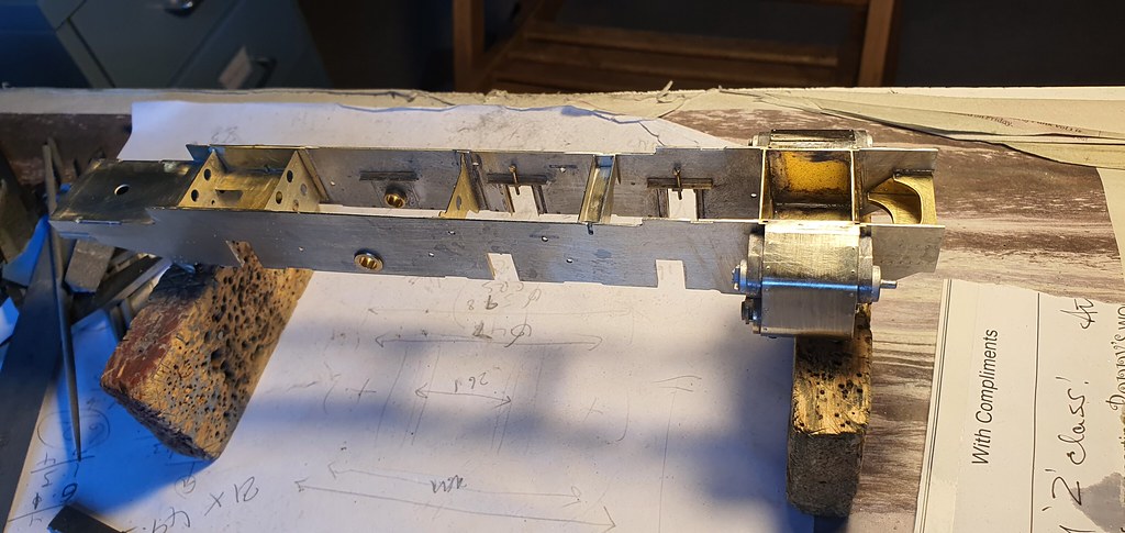
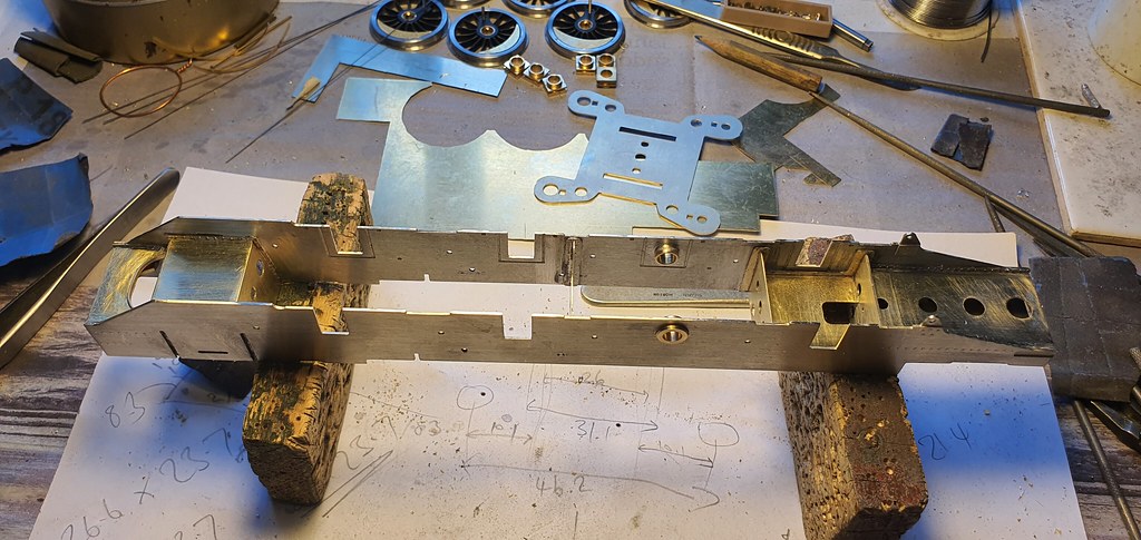
The frames are a pretty good representation of the real loco, well below the chassis at least. The bits of the chassis on view above the footplate are designed to be planted on the footplate, I'll deal with those bits later. The frame stays provided are very functional, but if you're building the inside motion and cylinder they're all in the wrong place except the rearmost. Luckily I have a GA so I just made what was on the real thing.


51258048375_c4e98c5f5b_b.jpg


51257752544_6e00f39467_b.jpg


51257206893_1c9c7c1743_b.jpg


51258048880_3409fa5706_b.jpg


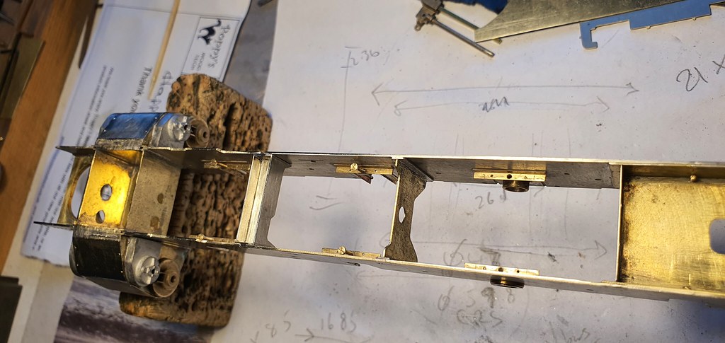
Anthony Garton of Poppy's Woodtech fame sent me one of his Loco Builder's Boxes to try out as a chassis building jig. Below is a short video of how I put the axle boxes in the chassis using the box. I suppose I should note this in the Register of Member's Interests (unlike Hancock and the rest,) although I only got a free box for making the video, no royalties. The box does make the process much easier though.


Thanks to Tito Puente


51258049265_9da8d97d80_b.jpg


One thing that won't make the job easier was the ridiculous way the boiler etch had been pre-rolled. It would have certainly been better left flat.


51256279722_f1403ac28b_b.jpg


I'll have to scratchbuild a boiler now. Thankfully the etch for the smokebox was salvegable.


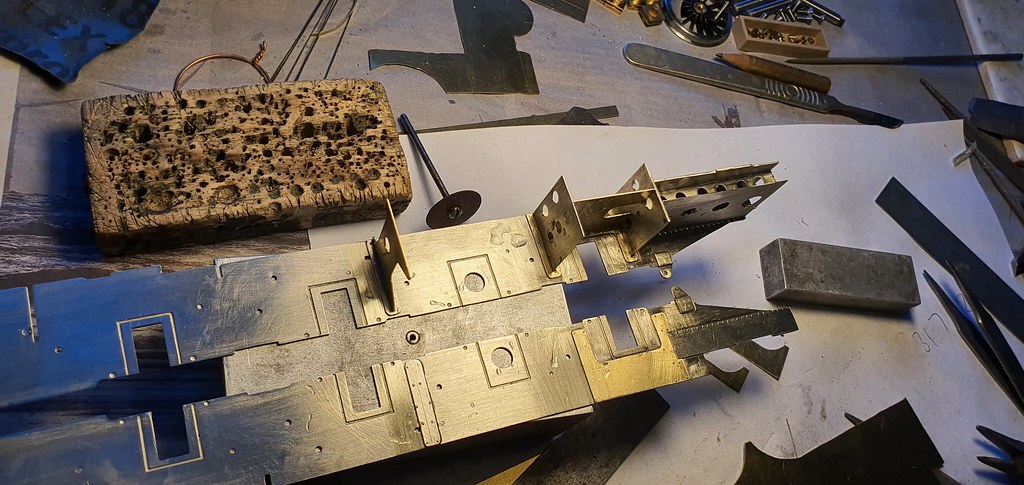
I also made a start scratchbuilding the outside cylinders. As I'd already gone a bit far off the script the etches provided for the cylinders didn't fit. They weren't quite right anyway.


51257753329_75b4aa3b12_b.jpg


More pics here: nick dunhill
 

Podartist79

Western Thunderer
Will be fascinating to watch this build through Nick, getting the ‘Dunhill treatment’ as Heather’s said.
Love all the extra work you’ve put in already - top class as always!
Neil.
 

Steph Dale

Western Thunderer
Nick,
Are you using the Laurie Griffin valvegear set on this? Does it include the inside motion as well?

Steph
 

simond

Western Thunderer
Hi Nick,

two questions,

when you used the Poppy box, you used one rigid axle to locate the frames, fore and aft and up & down. How did you locate the frames to get them horizontal? I might have missed it, but did you just sight across the box & frames and rely on the springs to keep it all in place, or was there some packing involved?

I wasn’t sure if you kept the rigid axle, or changed it for a spring one after fitting the other six axleboxes - the end of the vid shows the rigid bearings, but the picture above the interestingly rolled boiler seems to suggest that there’s another pair of horns in there?

Some years back Chris @Pencarrow made a comment about a Z and my coaling stage, the ramp of which is, shall we say, a little compressed lengthwise. In the admittedly unlikely circumstance that you find yourself on the south coast of Kent, with the said locomotive, we can see whether my predictions of its middle axles not touching the rails as it enters the grade, and the outside axles waving around in the air at the top are borne out :)

cheers
Simon
 

Nick Dunhill

Western Thunderer
Steph, yes my plan is to get the drawings of the inside motion from the NRM (was supposed to be going this morning then I was grounded by the Govt Test and Trace app!) and get Laurie to supply anything he has in his range that's suitable. It has an interesting variant of Walschearts with two eccentric sheaves involved. I only used the LGM coupling and connecting rods, didn't know he did any others......

Simon, I just eyeballed the frame across the top of the box and kept checking it before soldering each horn cheek. I did think about rigging up some kind of device for holding the chassis horizontal but didn't in the end. It worked well. I kept one axle rigid as a datum, and it'll be the driven axle so a bit more stable. Interestingly the Laurie Griffin cast coupling rod centres came out at scale and the etched axle holes in the DMR chassis a little under. Building the axleboxes this way compensates for that though.
 

Steph Dale

Western Thunderer
Yeah, the arrangement is very odd. Maintaining clearances around the axles will be a pain - one of the axles has a crank in it to clear the rods, if I'm remembering properly.

Mine's an ongoing scratchbuild - I started it in sixth form!

Steph
 

Nick Dunhill

Western Thunderer
According to the GA it has split drive. The outside cylinders drive the 3rd axle and the inside cylinder the 2nd.
 

Steph Dale

Western Thunderer
Yeah, that's definitely true - but there's a set in the leading axle to clear the reach rod that's used to drive the bottom of the combination lever.
It's all a bit of a phooey; the motion layout was originally configured for Holcroft derived motion, but changed to individual drive when it was realised that the overhang in front of the cylinders would be too great. That's why the middle cylinder and valve chest end up at the slightly odd angle.

In so many ways it's an odd little loco, but a fun prototype to model.

Steph
 

mickoo

Western Thunderer
It's the lower reach rod that has a set in.


1.jpg

Like Gresley engines the inside cylinder is inclined which does not give a true 120° - 120° - 120° crank arrangement. Only the piston is inclined, the valve is horizontal which can catch people out, the same applies to the LNER engines.
 

Steph Dale

Western Thunderer
Between us we'll get it right! :D

The valve isn't horizontal, Mick, you can see that in the drawing - it wasn't necessary for the Holcroft derived valve drive, but was for the Gresley equivalent. It's angled at the same rate as the inside cylinder. Good spot on the reach rod, though - I knew there was something funny going on there and don't have the drawings handy.

Nick, sorry for potentially leading you up the garden path. When you've got the motion arrangements hopefully it'll all become clear.

Steph
 

mickoo

Western Thunderer
Ah, the joys of GA's were everything is thrown onto the paper, but only half, and not always the same half :eek:

The pipe and rod isn't much more help either and I don't have sight of the inside motion drawing.....it's on the list to collect at some point.
 

Dave Holt

Western Thunderer
Without seeing the whole valve gear layout, it's not easy to make out the arrangement for certain. However, it doesn't appear to have a conventional combination lever and anchor link connected to the inside cross head. Instead, there appears to be a very short combination lever, suspended on a swing link at the valve rod level and connected at its lower end to the rod with the cranked portion. If so, this cranked rod is not a reach rod but a further eccentric rod to give the necessary movement to the bottom of the combination lever, in phase with the cross head but with a much shorter travel, perhaps from a second eccentric on the driven axle, as previously mentioned? The cylinder/valve inclination and super short combination lever are all necessary to clear the front coupled axle.
Dave.
 

Steph Dale

Western Thunderer
Without seeing the whole valve gear layout, it's not easy to make out the arrangement for certain. However, it doesn't appear to have a conventional combination lever and anchor link connected to the inside cross head. Instead, there appears to be a very short combination lever, suspended on a swing link at the valve rod level and connected at its lower end to the rod with the cranked portion. If so, this cranked rod is not a reach rod but a further eccentric rod to give the necessary movement to the bottom of the combination lever, in phase with the cross head but with a much shorter travel, perhaps from a second eccentric on the driven axle, as previously mentioned? The cylinder/valve inclination and super short combination lever are all necessary to clear the front coupled axle.
Dave.

Yep - that's correct. Neat description! :thumbs:

Steph
 

Martin Shaw

Western Thunderer
Dave has summed up the situation very neatly, I was struggling to get my head round it. It would seem that when Mr Maunsell designed the 3 cylinder engines, N1 and K class prototypes were fitted with Holcroft conjugated valve gear for the middle cylinder. This was unsatisfactory for some reason, on paper it as at least as good as Mr Gresley's version, and all subsequent SR 3 cylinder engines had 3 sets of Walschearts gear. What wasn't changed was the middle cylinder casting which wasn't ideally suited for Wal valve operation, why I don't know but the SR persisted with it on everything with 3 cylinders, with the thankful exception of the Schools. It had originally been intended that the Zs would have either conjugated gear or been a 2-8-0 to allow enough length for a normal middle cylinder arrangement without the front bufferbeam throw over being excessive. The latter would have made the min radius curve too great so they settled on the 0-8-0 arrangement, with significant side play on the front and rear axles, this limited space from the cylinder casting to the second axle so the folded valve gear with two eccentrics was devised. It seems a complex solution compared to conjugation, but no doubt adequate for the intended work.
Regards
Martin
 

Nick Dunhill

Western Thunderer
Well all will become clearer on thursday. I'm off to the NRM to photo some drawings and one is the inside motion drawing. Come back on friday for a full explanation. It's hard to see what's going on in the GA, too many things drawn on top of each other and too much left off. Thanks for your help though all.
 

Scale7JB

Western Thunderer
Well all will become clearer on thursday. I'm off to the NRM to photo some drawings and one is the inside motion drawing. Come back on friday for a full explanation. It's hard to see what's going on in the GA, too many things drawn on top of each other and too much left off. Thanks for your help though all.

If you should happen to find some LNER Y4 drawings on your travels..... :))

I need to get up there myself.

JB.
 

Nick Dunhill

Western Thunderer
So this week I was mainly finishing my BG Armstrong Convertibles, but did get something done on the Zs. I didn't like the look of the kit etches for the cylinders, and also they weren't going to fit as I'd made an inside cylinder. As you can see above I cut out parts for new cylinders. I made a test cylinder rear, using the GA as a guide and the cast DMR cylinder covers didn't fit. I assumed I'd cocked up some measurements so made another with the same result. I measured the diameter of the cylinder head covers on the GA and they came out at 12.5 mm diam or thereabouts, the cast kit items were 14 mm diam. So I reduced them in diameter and all was well.


51272199669_dd68b40e59_b.jpg


51271647773_1a7fc6fdda_b.jpg


These were soldered to the chassis and a motion bracket/stay for the inside cylinder fabricated.


51270722957_4ba9b12d52_b.jpg


51272200029_6e1c27e5ba_b.jpg


So I have asked Mr. Griffin if he'll sell me some eccentric rods and a big end crank and were good to make the inside and outside motion.
 
Top