Nick Dunhill
Western Thunderer
After my mammoth Z Class build it's nice to do a little palate cleanser. I was approached by a chap (who saw my build blog on the Z chassis) to construct him the chassis for a F7 V2 kit he had bought. I like to have a short build, from time to time, that just requires cutting etchings off a fret, reading the instructions and soldering stuff together. No cross referencing 3 drawings and no measuring and modifying.
Someone elso got wind of what I was doing and asked if I could build him one too, but with an inside crank/rod/slidebar etc and different compensation. Why not I thought, still straightforward. So I thought you might like to see what I had done and reflect on any issues that arose with the build. It isn't a comprehensive how-to-build a F7 V2 (as the customers didn't want to pay me to do the easy bits) but it does show the trickier bits of construction.
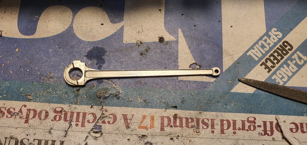
First off, as always, with a chassis build I always make the rods that require multiple laminations, in this case the connecting and coupling rods. The coupling rods will be used later to locate the axleboxes accurately.
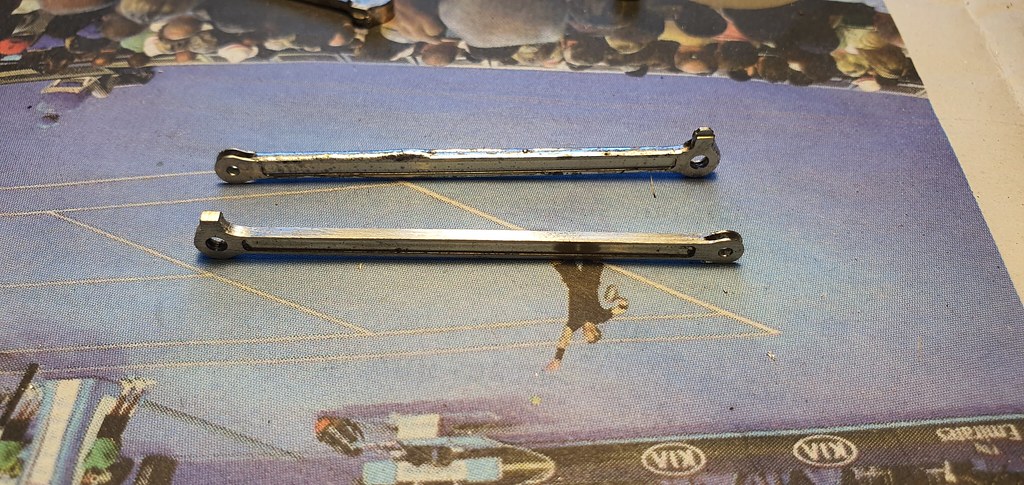
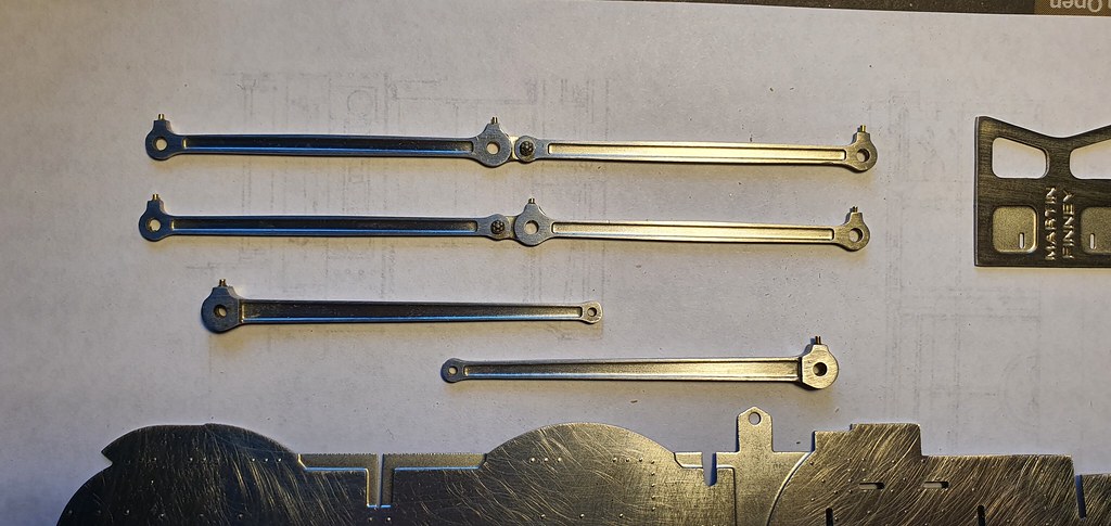
The secret here is to flood the laminations top and bottom with plenty of 145 solder and patiently file them up, it takes a day to make two sets of each.
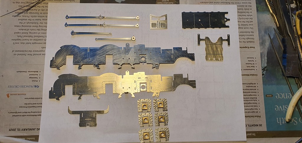
Next I prepared all the etches for the frames, spacers and horn guides. Again lots of filing and R4.
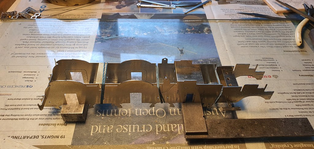
The above photo shows the unmodified chassis. It was constructed as suggested by F7 using the rocking beam-type compensation. The second chassis was built using the more usual bump-stops-and-downward-springy method. The inside cylinder gubbins required the big stay round the front driving axle to be left out, although I actually put part of the stay in position as it becomes the mount for the front pony truck. I also made the stay that supports the inside slide bars to stiffen the chassis frames in that area. I also modified the rear stays to look more like the cruciform LNER style item.

You can see that the rear section of the chassis had already been constructed by the owner and attached to the firebox stay as described later in the F7 instructions.

Here's the axleboxes being fitted up in the chassis, using the rods as a guide, with my trusty jury axles. A very free running chassis resulted. Both sets of rear driving wheels had clearance issues with the tyres and the sticky-up firebox stay arms. The stays had to be relieved a bit with a grinder and strengthening plates added to the rear.
The slidebars are a 6 etch lamination, they look daunting, but aren't. My advice is to (follow the instructions) remove the etching cusps first, all of them and carefully up to the edge of the etch. Then pin as in the instructions and flood with 145 solder. They're not as hard to get a nice finish as you might imagine. Perhaps easier than fettling some cast items that turn up distorted.....they always are....


Next was the splasher thingies, the cylinders and motion brackets. no issues there if you follow the instructions.

The chassis with AGH wheels had no conflict between the leading driver crankpin and the slidebars. Both Slater's and AGH wheels required shimming to remove any end float and the crankpin nuts replacing with thinner more prototypical items. The Slater's wheels have a thicker wheel boss which causes the crankpin nut to be in conflict with the slidebar. I thinned the top hat chassis 'rim' and removed a couple of thou off the inside edge of the rear of the slidebar. This generated clearance of about 0.4 mm which should be fine, unless your trackwork is really rubbish.

Someone suggested that I move the cylinder centres out slightly, but I descovered later that you can't without widening the motion bracket too. Widening the motion bracket would inevitably lead to modifications to the footplate and the eccentric rod being in the wrong position. Not going there!
A kind fellow modeller donated a F7 W1 inside con rod to the cause. They're the same length as a V2 item so it dropped straight in.


A light mod was required here to locate the outside motion bracket to the inner one.


The radius rods need to be joggled inwards slightly in front of the expansion link (the joggle can be hidden inside the motion bracket assembly.) In this way the radius rod front forked ends can be made to fall in line with the top of the combination lever, and the valve rod won't be pulled out of alignment. Both chassis were like this so a slight correction required? Maybe the radius rod tapers inward on the real thing, I haven't looked.
So that was two chassis just requiring the 2 in 1 levers and then the cylinder clothing. I'm hoping that they will allow their respective owners to have nice free running locos when they get round to finishing them!
Someone elso got wind of what I was doing and asked if I could build him one too, but with an inside crank/rod/slidebar etc and different compensation. Why not I thought, still straightforward. So I thought you might like to see what I had done and reflect on any issues that arose with the build. It isn't a comprehensive how-to-build a F7 V2 (as the customers didn't want to pay me to do the easy bits) but it does show the trickier bits of construction.
First off, as always, with a chassis build I always make the rods that require multiple laminations, in this case the connecting and coupling rods. The coupling rods will be used later to locate the axleboxes accurately.
The secret here is to flood the laminations top and bottom with plenty of 145 solder and patiently file them up, it takes a day to make two sets of each.
Next I prepared all the etches for the frames, spacers and horn guides. Again lots of filing and R4.
The above photo shows the unmodified chassis. It was constructed as suggested by F7 using the rocking beam-type compensation. The second chassis was built using the more usual bump-stops-and-downward-springy method. The inside cylinder gubbins required the big stay round the front driving axle to be left out, although I actually put part of the stay in position as it becomes the mount for the front pony truck. I also made the stay that supports the inside slide bars to stiffen the chassis frames in that area. I also modified the rear stays to look more like the cruciform LNER style item.
You can see that the rear section of the chassis had already been constructed by the owner and attached to the firebox stay as described later in the F7 instructions.
Here's the axleboxes being fitted up in the chassis, using the rods as a guide, with my trusty jury axles. A very free running chassis resulted. Both sets of rear driving wheels had clearance issues with the tyres and the sticky-up firebox stay arms. The stays had to be relieved a bit with a grinder and strengthening plates added to the rear.
The slidebars are a 6 etch lamination, they look daunting, but aren't. My advice is to (follow the instructions) remove the etching cusps first, all of them and carefully up to the edge of the etch. Then pin as in the instructions and flood with 145 solder. They're not as hard to get a nice finish as you might imagine. Perhaps easier than fettling some cast items that turn up distorted.....they always are....
Next was the splasher thingies, the cylinders and motion brackets. no issues there if you follow the instructions.
The chassis with AGH wheels had no conflict between the leading driver crankpin and the slidebars. Both Slater's and AGH wheels required shimming to remove any end float and the crankpin nuts replacing with thinner more prototypical items. The Slater's wheels have a thicker wheel boss which causes the crankpin nut to be in conflict with the slidebar. I thinned the top hat chassis 'rim' and removed a couple of thou off the inside edge of the rear of the slidebar. This generated clearance of about 0.4 mm which should be fine, unless your trackwork is really rubbish.
Someone suggested that I move the cylinder centres out slightly, but I descovered later that you can't without widening the motion bracket too. Widening the motion bracket would inevitably lead to modifications to the footplate and the eccentric rod being in the wrong position. Not going there!
A kind fellow modeller donated a F7 W1 inside con rod to the cause. They're the same length as a V2 item so it dropped straight in.
A light mod was required here to locate the outside motion bracket to the inner one.
The radius rods need to be joggled inwards slightly in front of the expansion link (the joggle can be hidden inside the motion bracket assembly.) In this way the radius rod front forked ends can be made to fall in line with the top of the combination lever, and the valve rod won't be pulled out of alignment. Both chassis were like this so a slight correction required? Maybe the radius rod tapers inward on the real thing, I haven't looked.
So that was two chassis just requiring the 2 in 1 levers and then the cylinder clothing. I'm hoping that they will allow their respective owners to have nice free running locos when they get round to finishing them!
Last edited:
