Building a shay locomotive

mike evans

Active Member
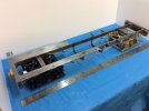
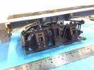
In the early part of this year I started scratch building a 3.5" Shay loco using Kozo's excellent book as my guide.
After a lengthy search I found the correct bevel gears and also placed an order for the boiler which should be here next week.
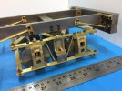
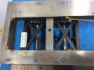
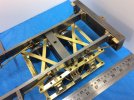
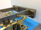
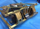
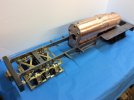
Here are a few photos of the work so far
IMG_0711.jpegIMG_0712.jpegIMG_0713.jpegIMG_0714.jpegIMG_0715.jpegIMG_0716.jpeg

i hope you enjoy these photos .
More photo as further progress is made
Mike
 

Nigel Cliffe

Western Thunderer
I look forward to seeing more.
I have the book by Kozo, along with the equally good book on the Heisler. Both from the days when I was dabbling in the model engineering side of things.
 

michael mott

Western Thunderer
That looks ambitious, I have Kozo's book on the Pennsy switcher, he does a great job of walking one through the steps to build a decent looking model.

Michael
 

mike evans

Active Member
That looks ambitious, I have Kozo's book on the Pennsy switcher, he does a great job of walking one through the steps to build a decent looking model.

Michael
Ambitious yes and certainly challenging which makes life more interesting.
As you rightly say, Kozo shows in what order to carry out the machining which saves lots of time in puzzling over the drawings and finding out, with one more task on the lathe, there is no way of holding the part. We’ve all been there haven’t we?
More to follow.

Mike
 

Boxbrownie

Western Thunderer
That looks nicely miniature “heavy engineering” will be following this, I am trying to remember how the Shay delivers the power, isn’t it to bevel gears onto the outside of the bearing/axles? Is there a key way or some such onto the end of the axles?
 

mike evans

Active Member
That looks nicely miniature “heavy engineering” will be following this, I am trying to remember how the Shay delivers the power, isn’t it to bevel gears onto the outside of the bearing/axles? Is there a key way or some such onto the end of the axles?
Thanks for your interest. Yes, the power is via bevel gears.
The small bevel gear has major surgery. The boss is machined away and a new boss made and silver soldered on the side of the gear teeth and care has to be taken that the solder does not go onto the teeth.
The large gear also has the boss machined away and the inside face thinned followed by 4 holes drilled and counter sunk. Corresponding holes are drilled in the wheels and tapped 2.5mm for c/s screws.
So, the gears are fixed to the wheels which are drilled and reamed 8mm providing a sliding fit. These are then glued with Loctite 643 to the axle which has been turned to 8mm at each end.
Hope the answers your question.

Mike
 

mike evans

Active Member
So the drive will be inside the bogie frame?
Hello Boxbrownie
The short answer is no.
The horizontal drive shaft runs in holes drilled and reamed in the journal boxes. There are sliding joints and universal joints to allow to allow the bogie frames ( or trucks as the drawings say) to turn.
Please see the enclosed photo.


251C6311-1C15-4E56-8923-9A13B7D52B08.jpeg

Hope this answers your question

Mike
 

Ian@StEnochs

Western Thunderer
The bogie looks to be rigid. I would expect the real thing to have sprung axleboxes especially as the prototype was used on some pretty rough track. Is the solid arrangement just for the model? Springing would certainly increase the complication.

Ian.
 

mike evans

Active Member
The bogie looks to be rigid. I would expect the real thing to have sprung axleboxes especially as the prototype was used on some pretty rough track. Is the solid arrangement just for the model? Springing would certainly increase the complication.

Ian.
Hello Ian
If you look closely at the middle of the photo you will see two springs which give overall springing and the far side axle boxes also have springs to give more local springing.
Hope this answers your query.

Mike
 

Ian@StEnochs

Western Thunderer
Hello Ian
If you look closely at the middle of the photo you will see two springs which give overall springing and the far side axle boxes also have springs to give more local springing.
Hope this answers your query.

Mike
Thanks Mike.

I noticed the springs and assumed that they were for the central bolster carrying the loco weight. As I understand it the two axleboxes on the gear side of the bogie are rigid with the frame and the two on the other side are able to follow track iregularities. Fine in miniature but is that how the prototype worked?

Ian.
 

mike evans

Active Member
Thanks Mike.

I noticed the springs and assumed that they were for the central bolster carrying the loco weight. As I understand it the two axleboxes on the gear side of the bogie are rigid with the frame and the two on the other side are able to follow track iregularities. Fine in miniature but is that how the prototype worked?

Ian.
Hello Ian
Looking st some photos of the ‘real thing’ the horizontal drive shaft goes through the journal boxes which in turn are bolted to the truck (bogie) frame. As this shaft carries the small bevel gear which meshes with the gear on the axle, I can only assume that these are rigid.
What do you think?

Mike
 

Yorkshire Dave

Western Thunderer
I noticed the springs and assumed that they were for the central bolster carrying the loco weight. As I understand it the two axleboxes on the gear side of the bogie are rigid with the frame and the two on the other side are able to follow track iregularities. Fine in miniature but is that how the prototype worked?

Hi @Ian@StEnochs - this might give some clues as to how Shay trucks were sprung. https://www.shaylocomotives.com/trucks/trucks.htm

It looks like the journals are sprung in the trucks on the non-geared side only.
 

Ian@StEnochs

Western Thunderer
Mike & Dave,

Thank you that does explain the principle. There is quite a lot of info online and lots of very interesting pictures. Shay’s were slow speed locomotives for logging, so fancy springing was not really required, Dave the drawings you bookmarked are excellent and show that the trucks were basically wagon/car bogies.

Ian.
 

Boxbrownie

Western Thunderer
Hello Boxbrownie
The short answer is no.
The horizontal drive shaft runs in holes drilled and reamed in the journal boxes. There are sliding joints and universal joints to allow to allow the bogie frames ( or trucks as the drawings say) to turn.
Please see the enclosed photo.


View attachment 175282

Hope this answers your question

Mike
Aha I didn’t notice there was room twixt wheel and axle box, excellent.
 

Boxbrownie

Western Thunderer

mike evans

Active Member
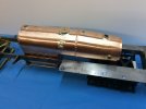
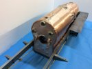
Big leap forward today as the boiler arrived. This boiler has been TIG welded so none of the plates have been flanged.
At the moment the welds are clearly visible but these will be covered by the .3mm brass wrappers.
Has been tested to 200 psi and a test certificate issued. The running pressure is 100 psi.
On with the smoke box and lots of miniature plumbing.

Here are a few photos


93A741DB-FF48-42C7-8373-72E0D7F09E61.jpegF9EF9141-CAC9-4FD3-BBE0-963985F95427.jpeg0ACB53F7-4B04-4FB3-8C86-2780DF7BF35E.jpeg
Hope you find this interesting.

More to follow-eventually

Mike
 

mike evans

Active Member
Your Shay is coming along very well indeed Mike.

Can you tell us who the boiler maker is?

Cheers

Dave
Hello Dave
The company I used for the boiler was Steam Technology. Co.uk. First came across them at the Model Engineering exhibition at Ally Pally about 4 years ago.
Earlier this year I sent enquires to four companies and only two responded, Steam Technology being one of them. The other came from the West country and wanted 24 months lead time and twice the price. Both companies required 50% deposit.
No complaints, helpful and on time.

Mike
 

Dangerous Davies

Western Thunderer
Hello Mike
I wasn't aware of Steam Technology, another one to add to my list. Will you fit one injector and an axle pump or two injectors?

Cheers

Dave
 
Top