Ceci n'est pas une pipe - after the deluge: reworking Ratio

AJC

Western Thunderer
Because, of course it's actually a Tube, so far as BR was concerned. Anyhow, hopefully you'll excuse the allusion to Magritte.

Well here we go, my contribution to this exercise, the reconstruction of an ancient Ratio GWR Open C, so four planks in height. This, part of a collection acquired from a late, fondly remembered, club member has already been reworked once, with D&S w-irons but not a lot else. I rather like long opens - later pipe wagons included - because they weren't only use for the carriage of tubes but for anything that would fit - bulky but light(ish).
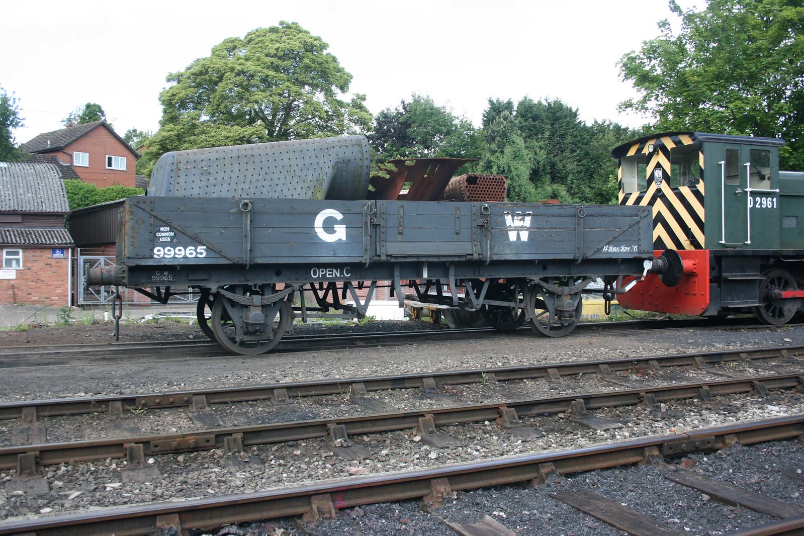
IMG93671 GWR Tube-Open C 99965 SVR Bridgnorth 6 June 15 by Dave58282, on Flickr

This time the whole chassis and solebars will go and the result will - with the aid of some etches from the Scalefour Society - end up as a diagram O.19 (I think). In any event, here's an example as preserved on the Severn Valley: GWR 99965 Open 'C' Goods Wagon - SVR Wiki and another from Paul Bartlett's collections at Llangollen: GWR Open C and GW/BR Tube diag 1/446 ZYP | W94869 Open C and another wagon more recently there: 94864 GWR 4 Plank Open 'C' - Llangollen Railway 16.06.14 Mick Cottam

More when the etches arrive. If this turns out to be relatively simple then I'll follow up with a Parkside Pipe...

Adam
 
Last edited:

AJC

Western Thunderer
And here are the photos of our victim/starting point:

Open_C_001.jpg

The chassis is vintage Ratio and not bad, considering the circumstances. As noted the W-irons are from D&S and will be recycled at some point since they're perfectly good. The Ratio kit represents a diagram O8, apparently (GWR 4mm Wagon and Van Kits) and this has knock on effects for the conversion. The body will need replacement doors with a barrow plank and feathered top edge - it's currently straight up and down - and some new strapping on the ends. Meanwhile, the chassis will go from lever brake to Dean Churchward.

Open_C_002.jpg

The reason for the separation of parts is fairly obvious and common to many older wagon models: Evo-Stick (and possibly reinstatement with UHU). The buffers, being the usual flimsy Ratio affairs, have gone the way of all flesh and will be replaced with something more durable from Lanarkshire Models. One of the things that a replacement chassis will achieve is to bring the solebars in to a more plausible position - the overhang of the body is quite pronounced in reality - the ten spoke wheels will almost certainly end up in the spares box, too.

Adam
 
Last edited:

AJC

Western Thunderer
Sorry about the rather grotty picture, but it should even so be clear what I've done. After demolishing bit of the underframe it became clear that the floor would be willing to part itself from the body. Obviously the body is now in two bits but no matter; inscribing planks on the inside will now be much easier.

Open_C_003.jpg

Planks apart, the next job is to make up a nice new floor from 40 or 60 thou' ready for the etched chassis.

Adam
 

AJC

Western Thunderer
With the new floor installed, I was able to cut out and replace the doors. The new floor was necessary first to give the sides some structural support while the doors were removed. I think it's worked out ok:

Open_C_004.jpg

You should be able to see the top and bottom angled planks outside and in - the interior angles are simply filed and planed into the sheet, while the exterior plane is formed from strip a plank height deep, chamfered off and stuck on. That will do until the chassis has arrived and been assembled.

Adam
 

Jim smith-wright

Western Thunderer
You seem to be predicting my own workbench Adam. I’ve got a SR brake and one of these half done! What chassis are you going to use?

Jim
 
  • Like
Reactions: AJC

AJC

Western Thunderer
You seem to be predicting my own workbench Adam. I’ve got a SR brake and one of these half done! What chassis are you going to use?

Jim

Hi Jim,

I'm going to try a Morgan Designs etch from the Scalefour Society: WN4520 | E-Shop | Scalefour Society

The plan is to also use the additional etched solebars - unfortunately I've just had the wrong ones sent (easily sorted, I'm sure). To be honest, I probably have the bits in stock, with the brake mouldings from the original chassis that would do the job, but I'm interested to try one having read a little about them on the Scalefour forum. This with it's longish wheelbase seems a likely candidate.

Adam
 
Last edited:

AJC

Western Thunderer
The correct solebars have now been received and we can get on and here's where we're at:

Open_C_006.jpg

The basic floorpan folded and soldered up which reveals the unusual elements of the design, explained in the (to my mind) excessively wordy and poorly laid out instructions: https://www.scalefour.org/downloads/gwunderframes2014s.pdf

More on those and the design features of the chassis later, but here's the rest of the etch; I will move further as and when I can find another 10BA nut (not supplied).

Open_C_005.jpg

Adam
 
Last edited:

AJC

Western Thunderer
I am less an less enamoured of the instructions for this chassis, though the etches themselves are growing on me. That said, my aversion to building anything exactly as designed has already caused me to stray from the engineer's intentions.

The design is quite unusual since it is basically a form of three-point compensation but instead of a rocking W iron at one end, it uses transverse springs with a built-in height adjustment using a 10BA screw acting on a captive nut. This obviously means that all W irons are static removing the need for mucking about separating springs and axlebox mouldings with the consequent visual disruption. Fair enough, but the instructions miss the key drawing/photograph which shows how the complete set up should look...

Open_C_007.jpg

The picture in the post immediately above shows that W irons are only etched onto the fold-up floorpan on one side. On the opposite side the W-irons form independent fold up units located via a tab and slot and secure with a captive 10 BA nut and screw. the intention (and it may be in the instructions, somewhere - tl;dr*) seems to be to avoid springing the W irons outwards to admit the wheels which is understandable but smacks of over-engineering given the tiny amount of flex needed. In any event, I've run out of 10BA nuts... Having worked this out I soldered the fixed end of the arrangement in maintaining alignment with a bit of scrap etch and the wheelset springs in and out perfectly well. The other end will be built as designed since I can see the benefit of the adjustable W iron in setting up the springs, I think.

One other quirk concerns the solebars: these are nicely etched with scale-thickness half-etched flanges and a detail overlay but are about 0.75mm deeper than the sides of the fold-up floorpan, and yes, they are the correct depth for the prototype! This doesn't exactly matter - indeed, it will allow another layer of plastic sheet to screw the chassis to, hopefully without the screw tip poking through the floor - but it seems an odd design choice for a bespoke chassis to suit a particular wagon type. Despite all this, the bits fit together and look right and having done one, the general design principle is obvious and should apply across the range which is extensive.

The instructions contain much of interest, including a treatise on Dean/Churchward wagon brakegear but the layout, order and sheer wordcount are unhelpful [there's also the jig that isn't described as a jig on the etch, the duplicated spring adjuster which doesn't seem to be needed or described as a spare, inconsistent terminology, lots of extraneous, rather didactic, text about flux and soldering and so on].

Adam

* tl;dr = too long; didn't read: you may think the same about this entry. ;)
 
Last edited:

AJC

Western Thunderer
A bit more construction (and instruction-based confusion and associated errors: yes, I inadvertently mirrored the brake fittings) with the brakegear started. Just the shoes and push rods thus far as I cannot quite work out the linkages from the instructions - it's obvious where the bits go, just not which way round...

Open_C_008.jpg

The above pic' shows up one of the things I'll need to attend to on the body - the diagonal bracing is a mite too subtle for my tastes and will be renewed. Side on and the profile shows good progress, I think.

Open_C_009.jpg

Adam
 

garethashenden

Western Thunderer
I agree with your comments about the instructions. I've built one and it worked and I've got a couple others to build. I think most of the problem with the instructions could be fixed by a good editor. Even if they were just separated by type it would make a big difference. One set of instructions for DC brakes, one for Clasp, and one for Morton, or something along those lines. I found the 78 page pdf to be reminiscent of a choose-your-own-adventure where you keep coming across instructions to turn to a given page number to continue your project. I think the instructions for Runmey Models underframes shows how it should be done. He groups similar kits together but doesn't try to make a single master set of instructions for the whole range.
 

AJC

Western Thunderer
I agree with your comments about the instructions. I've built one and it worked and I've got a couple others to build. I think most of the problem with the instructions could be fixed by a good editor. Even if they were just separated by type it would make a big difference. One set of instructions for DC brakes, one for Clasp, and one for Morton, or something along those lines. I found the 78 page pdf to be reminiscent of a choose-your-own-adventure where you keep coming across instructions to turn to a given page number to continue your project. I think the instructions for Runmey Models underframes shows how it should be done. He groups similar kits together but doesn't try to make a single master set of instructions for the whole range.

Hi Gareth,

Separating the prototype detail into one file and the instructions themselves into another would be a start, as would adding a couple of additional drawings. Justin also goes back and revises his instructions periodically as well (adding page numbers, for example). I wouldn't claim to be a good editor, but I do it professionally; were I a member of the S4 Society I'd have offered already after this experience. Since I'm not, and I have little enough free time I'll pass, for the moment... That said, the etches themselves are not at all bad and go together well; they'll take this wagon to a higher level than I'd have achieved left to my own devices.

Adam
 

AJC

Western Thunderer
Here are versions of the two pictures absent in the instructions but which would make everything clearer.

Open_C_010.jpg

Note the linkages; I've worked out the fit from the shape rather than the text (though it's in there) and the ratchet, below which made up reasonably easily - there's a good sketch which makes matters clear but which fails to show how the linkages connect with it...

Open_C_011.jpg

Blurred - I'll retake, later.

Adam
 

AJC

Western Thunderer
Having finished the chassis, and fitted the final W iron, this time as the designer intended (I won't be doing that again as I really can't see the point), body and chassis are now permanently bonded (epoxy). Before doing all that I soldered the number plate to the solebar; it's legible, but I won't be numbering the wagon accordingly.

Open_C_013.jpg

The headstocks will be in plastic and the top flange is already fitted; the patchiness of the metal black emphasises my rather splashy soldering, but never mind. Note that I've also removed the diagonal strapping which I'll reinstate when I've got to grips with exactly which variant of the Open C I'm doing. The differences between different diagrams of Open C boil down to changes in Swindon's ideas about fixing the body to chassis and some are easier than others; the O.19 is probably the most straightforward, the O.24 is similar but has more solebar brackets, while the O.34 would probably require wholesale replacement of the side strapping: GWR Open C and GW/BR Tube diag 1/446 ZYP | KDW136500 TUBE [01]

So far as I can tell, the chassis for all of these is more or less identical so the note of the etch that this converts an Open C (David Geen, presumably) to an O.18 isn't quite right.

Open_C_012.jpg

Adam
 

AJC

Western Thunderer
Coming back to this as it's cooled down a bit and more to the point since I've finished mucking about with paint for the moment. Where were we? Detailing, and lots of fiddly solebar brackets in particular. Of course, there's also springs and axleboxes; next, lots of bolt heads, the curious lashing rings at the top of the side knees (I think they are) and that's surely about it.
Open_C_015.jpg

Adam
 

AJC

Western Thunderer
Beautiful ... this is hard to believe this is 4mm!!! I love the detail of the rope loops and chains.

Julian

Well you've clocked the bits I added which demonstrates that it was worth it, I suppose! The wonders of the macro lens. The point - if there is one - is the texture added by these minor details adds to the eventual overall picture. Really, I just like doing this sort of thing and this particular wagon has come out well. I must get around to the load I had in mind for it though.

Adam
 
Last edited:
Top