Chas Levin

Western Thunderer
Hello all, this workbench thread will cover my various modelling activites - mainly, but by no means exclusively GNR and LNER.
Like a lot of people, I left the RTR railway and the mainly military Airfix kits of my youth and didn't return to modelling for about 30 years, by which time a renewed interest in railways and a very different railway kit industry suggested building railway vehicles, something that hadn't occurred to me before.

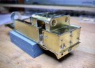
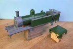
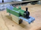
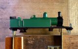
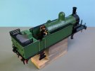
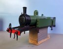
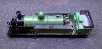
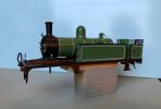
I posted a photo of part of my current project - the loco body of a 4mm OO gauge London Road Models GNR C2 (later the LNER C12) - in my first post in the New Members section and a couple of replies mentioned that people are very keen on lots of photos here: I hope they meant it!

I thought I'd start with a potted history of this current build; I always take a lot of photos as I work (I find them very useful later on in the build and if and when I build something similar later on, not to mention if an older model needs dismantling) so I've no shortage of material. I've tried to keep to a minimum for routine parts of the process, with a few more photos - and some explanation where necessary - for things that may not be quite so obvious.

So, here goes - the first few should be self-explanatory:
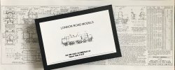
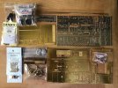
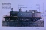
1 LRM C12 20200828 Box+plan.jpg
2 LRM C12 20200830 Unstarted.jpg
5 LRM C12 20200916 (5) Side-tanks.jpg
6 LRM C12 20200927 (2) Boiler & cab roof.jpg
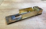
7 LRM C12 20201001 (1) Body parts & fold-ups.jpg
This was my first etched loco and only my second loco build of any type (the first was a DJH WM J9 on a rigid chassis) and I wanted to try out some form of compensation, so I took the superstructure up to the collection of pre-fabricated sections you see in the last photo, before breaking off to learn about compensation, eventually deciding to try a Flexichas-style compensation beam as my first attempt.
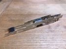
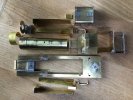
8 LRM C12 20201028 (4) Frames.jpg
You can just see in the above picture of the frames that they taper in quite a bit at the back; this was a slight modification of the kit to accommodate the rather tight curves on my layout and I also deviated from the LRM instructions by incorporating LRM's Radial Truck etch - usually supplied with some of their LNWR kits but also available separately. Happily for me, it is actually prototypical for the particular C2 I'm modelling!
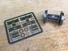
9 LRM C12 20201031 (1) LRM Radial truck.jpg
The truck fits into the same cut-outs in the frames that you'd use for hornblocks and below you can see the central lateral guide spring (that goes through a little eye in the top of the truck) and the two vertical tracking springs that keep the truck where it needs to be.
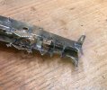
12 LRM C12 20201208 (2) Radial spring-guides.jpg
The hornblocks - which are on the front drivers, the compensation beam running between them and the front bogie - are MJT and I mounted the cosmetic etched springs for that axle on removable pieces of 1mm x 1mm brass angle secured by 14BA bolts, so the axle can be dropped out if needed:
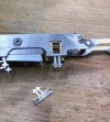
10 LRM C12 20201114 (3) MJT hornblocks.jpg
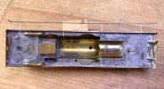
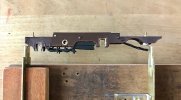
The compensation beam took a little thought, as to how it would have the desired weight distribution effect on the bogie, whilst still allowing free lateral movement - the usual problems of course, but all new to me. I used a piece of U-section brass with a hole in, bound to the slightly angled end of the beam with tinnned copper wire before everything was soldered and cleaned up, as a combined weight transmitter and rubbing plate. The bogie's securing guide bolt comes down from the chassis above, going through both the bogie stretcher and the rubbing plate - hopefully the picture below makes it clearer:
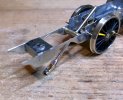
13 LRM C12 20201208 (8) Beam rubbing guide.jpg
15 LRM C12 20201211 (1) Chassis.jpg
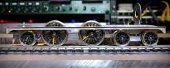
Everything came together quite nicely at this point and the chassis ran well, using a Mashima 1024 in a High Level Kits RoadRunner+ gearbox; LRM supply a one-stage Romford fold-up but because I wanted to drive the rear axle without intruding into the cab, I needed to fit the drive unit inside the firebox and boiler but partly underneath the cab floor, where the RR+ drive stretcher was an excellent solution. Plus, to be honest, I wanted to try making my own gearbox:
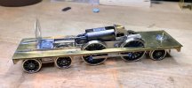
17 LRM C12 20210118 (1) GB, footplate & chassis.jpg
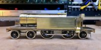
18 LRM C12 20210122 (2) GB, FP, Chassis, tanks & boiler.jpg
Right, I think that'll do for a first installment. I read the post about preferred photo size and I've resized everything so it should be within the requested limits - please let me know if not, as I did leave one or two a little larger where detail is relevant.
More to follow...:)
 

adrian

Flying Squad
Right, I think that'll do for a first installment. I read the post about preferred photo size and I've resized everything so it should be within the requested limits - please let me know if not, as I did leave one or two a little larger where detail is relevant.
They all look good to me and it's a nice tidy build.

Although left slightly puzzled by the yellow tape on the driver spokes - is this some special tactic to indicate left and right hand side drivers?
 

Chas Levin

Western Thunderer
They all look good to me and it's a nice tidy build.

Although left slightly puzzled by the yellow tape on the driver spokes - is this some special tactic to indicate left and right hand side drivers?
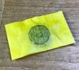
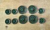
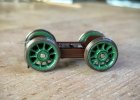
Morning gents, neither: I have several locos to build in due course with the same sized drivers and although some say that Romford/Markits can be removed and replaced many times with no ill effects, others contradict that with tales of worn hole edges leading to a slightly sloppy fit. I followed a tip I read somewhere and bought a secondhand set to use during builds, only putting on the final set once things were near complete. My experience bore out my caution - the yellow set came on and off many, many times during chassis fettling!
I painted a spoke yellow on each one of the test set to avoid mixing them up - although they were secondhand, they didn't look it.
Later on I was also able to use one to test ways of masking and painting the wheels, without having to worry about possible harm to the cork insulating layer or stubborn paint residue.
 

Chas Levin

Western Thunderer
Nice to see you put a radial axle at the rear. They make the loco run so much better than a pony or a wobbly axle.
Morning Peter, with tight curves to accommodate I read up a bit on tips and tricks and this seemed a good idea from a track geometry and holding point of view, especially as LRM sell that etch separately. And I can confirm it does run very well with it there. I'd intended hiding it quietly underneath and hoping no-one noticed, but after beginning work on it I read a new (to me) source on the history of these locos and discovered that some - including the one I'm modelling - had them fitted anyway. Which made me very happy:D
 

Chas Levin

Western Thunderer
Part two of my LRM GNR C2 build and next came boiler fittings, cab roof (made to be detachable, secured by two 14BA bolts, another new technique for me and a very useful one) and various other small soldered details:
19 LRM C12 20210129 (2) Boiler fittings.jpg
20 LRM C12 20210326 (1) Bunker & roof fittings 2.jpg
21 LRM C12 20210203 (4) Bunker & roof fittings 1.jpg
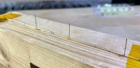
I then decided to add some pipework - not inclluded in the kit - and was generously helped by some fellow modellers on another forum. I'm very pleased I decided to try doing this: it took a lot of work, but I think it adds an lot to the model. The long runs of both vac and steam pipes were secured by small pieces of 0.45mm wire, soldered into holes in the tubing and then into corresponding holes in the valances and then trimmed:
22 LRM C12 20210317 (6) Vac & Steam pipes 1.jpg
23 LRM C12 20210317 (9) Vac & Steam pipes 2.jpg
24 LRM C12 20210304 (1) Vac & Steam pipes 3.jpg
Making tiny elbow joints from slightly larger diameter tubing and joining straights and elbows with brass wire was fiddly but satisfying:
25 LRM C12 20210305 (1) Vac & Steam pipes 4.jpg
26 LRM C12 20210308 (1) Vac & Steam pipes 5.jpg
27 LRM C12 20210320 (3) Vac & Steam pipes 6.jpg
Around this time I noticed that the tapering of the rear frame ends didn't look too good from the rear or sides of the loco, something not obvious with the chassis on its own, so I made two cosmetic pieces to give the illusion from the back and sides that the frames continue parallel - they don't look very impressive from this angle but they do the trick from normal viewing positions:
29 LRM C12 20210324 (6) Rear frame taper & false pieces.jpg
I also sorted out a NEM socket (I'm afraid I'm a tension lock man, because of RTR compatibility!) using the same bolt that secures the chassis:
30 LRM C12 20210329 (3) NEM pocket, rear coupling.jpg
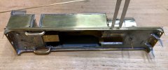
The above photo also shows the cosmetic frame ends from another angle, the radial truck with its securing wires, the pipe runs terminating in the frame end pieces (prototypical too, though it took me a while to find a photo showing exactly where the pipes do actually go...) and the underside of the High Level RoadRunner+ gearbox.
Next was brake gear and I received further help from fellow builders as to the advisibility of this being detachable:
31 LRM C12 20210416 (3)  Brake rigging 1.jpg
32 LRM C12 20210401 (4) Brake rigging 2.jpg
33 LRM C12 20210401 (5) Brake rigging 3.jpg
The rather tortuous looking pickups were intended to remain in place when the brake rigging pivots downwards, but I later simplified them!
With the addition of various other bits and bobs to the body, the business of painting was the next thing to consider...
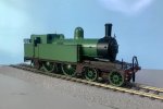
34 LRM C12 20210425 (2).jpg
 

AJC

Western Thunderer
Very nice indeed, Chas. I especially like the properly modelled vac’ pipe run. Relatively easy to do but not always present.

Adam
 

Dave Holt

Western Thunderer
Chas,
Very nice, especially the pipe runs. I might be wrong, but it looks to me that you have the handbrake lever pointing the wrong way. I think it should point towards the rear of the loco.
Dave.
 

Chas Levin

Western Thunderer
Very nice indeed, Chas. I especially like the properly modelled vac’ pipe run. Relatively easy to do but not always present.

Adam
Thanks Adam; now I've done a set and know what's involved I'll do things like that in future - I must thank Daddyman (whom many will know from various forums) for his considerable help in learning how to do them for this loco. It's funny how things you'd never previously noticed jump out at you once you're familiar with them, isn't it?
 

Chas Levin

Western Thunderer
Chas,
Very nice, especially the pipe runs. I might be wrong, but it looks to me that you have the handbrake lever pointing the wrong way. I think it should point towards the rear of the loco.
Dave.
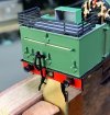
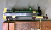
Hello Dave, oh dear - I hope not! Do you mean the lever that's beneath the footplate, shown in the fourth from last photo, of the inverted loco in the foam cradle? The instructions are only written for the brake rigging, but I found a diagram for a Bill Bedford replacement chassis that made things a little clearer.
Most of all though, given the location of the horizontal rod on which that handle pivots and that of the vertical rod that goes up through the cab floor, it didn't seem possible to fit it any other way.
 

Chas Levin

Western Thunderer
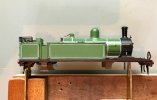
And so to painting: I'd originally intended this loco to be in plain LNER black, but I found myself wondering whether I could do it in GNR livery (part of an increasing interest in pre-grouping) and once the idea had occurred... I had to follow it!
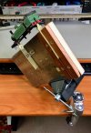
I'd only painted single colour vehicles and lined teak coaches before, but this is a different order of job, so I bought a copy of Ian Rathbone's "Modeller's Handbook of Painting and Lining" and started reading up a bit. Amongst the enormous amount of useful info in his book, Ian showed the lining stand he designed, built and uses: it looked just the thing (I find holding and positioning things while painting quite difficult) so I built one and I have to say it's one of the most useful things I've ever made:
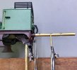
36 LRM C12 20210426 (1) Lining stand.jpg
37 LRM C12 20210426 (3) Lining stand.jpg
It's usefulness doesn't stop there - by holding the whole thing in a vise with a ball and socket mounting, any angle and position is possible:
72 LRM C12 20211231 (6) Lining stand + vise 1.jpg
And of course you don't have to use both of the brass mounts - I used it to hold the bogie while lining the smaller wheels:
45 LRM C12 20210527 (2) Wheel lining 4.jpg
And with the addition of a simple brass clip and a motor, larger wheels too:
44 LRM C12 20210426 (17) Lining stand, wheel lining 3.jpg
(The Portescap is for a future project and needed cleaning out, re-lubing and running in, but it's excellent slow running was very helpful).
However, I've got a little out of sequence!
After building the stand, I looked at painting the wheels. the main GNR Light Green was based on the Phoenix Precision Paints enamel, which I had matched by Express Paints into cellulose aerosols and I wanted to use them for the wheels too, to ensure the best possible match to the body. I know it's common practice to spray wheels all over and then clean off the tyres, but I thought I'd try masking: I haven't used masking tape or multiple colours much before and I still get a thrill from peeling off the tape and seeing only the desired areas have been painted!
38 LRM C12 20210430 (1) Wheel painting 1.jpg
39 LRM C12 20210430 (4) Wheel painting 2.jpg
40 LRM C12 20210430 (5) Wheel painting 3.jpg
46 LRM C12 20210528 (1) Wheels lined.jpg
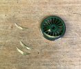
At this point, I realised to my horror that I'd forgotten the balance weights and worse, with the layers of primer and paint in place already, the kit's NS ones were a little too thick and sat too far proud of the rims, so I had to make new ones from 5thou brass and touch in the paint afterwards:
47 LRM C12 20210621 (6) Wheel balance weights.jpg
Then on to chassis painting and lining - on the newly built stand, Phonix Precision, brushed - and body priming - Halfords Etch Primer:
49 LRM C12 20210609 (1) Chassis lining.jpg
50 LRM C12 20210530 (1) Body primed.jpg
And I now know there's a 16 picture limit per post, so I'll carry on in a new post!
 

Chas Levin

Western Thunderer
I decided to try out some more masking tape, partly just to see how reliable an edge I could achieve for a particular colour; the following sequence includes the Express Paints GNR Light Green cellulose and Halfords Matt Black aerosols, followed by brushed Phoenix Precision GNR Frames Chocolate Brown, Satin and Gloss Black, Buffer Beam Vermillion and some touches of gold and red on the backhead:

51 LRM C12 20210614 (6) Body & roof light green.jpg
52 LRM C12 20210624 (3) Smokebox black.jpg
53 LRM C12 20210629 (7) Below footplate brown.jpg
54 LRM C12 20210714 (8) Brushed black, backhead etc.jpg
55 LRM C12 20210714 (15) Buffer beam.jpg
56 LRM C12 20210609 (5) Bogie.jpg
And this was where things reached, before the start of the main body lining, which seemed a good point to take a break and run the loco a bit:
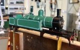
57 LRM C12 20210723 (1) Loco so far 1.jpg
And also a good point tonight to take a break, and go to bed ;)
 

Chas Levin

Western Thunderer
Very nice, I like the masking method for the wheels I may try it next time rather than the narrow strips I normally use.
Thanks Peter; I used Tamiya low-tack tape (bought mainly for use over existing paintwork) and after the full piece was on, I went round the rim with a razor, very slowly and carefully, under high magnification, because I'm continually learning how even tiny deviations from straight lines or from what should be perfect curves or circles stand out. Even so, they're by no means perfect but they pass muster from a distance. Since that last photo was taken I've improved the bogie wheels, where the painted and blackened areas didn't quite meet. The crank pins, axles and axle nuts used during spraying were also from a set of 'painting spares', which can then be cleaned up another time, leaving the ones intended for the current build clean and ready to use.
 

Chas Levin

Western Thunderer
I tend to use bits of various size cable sleeving to protect things like threads.
Nice idea Peter - I should have thought of that! I keep trying to wrap small pieces of masking tape round things like bolt threads and it doesn't grip very well because the pieces are too small.
 

Chas Levin

Western Thunderer
The next stage was the lining of the body. I started small, with the buffer housings. They're awkward to do, needless to say, so I took a piece of grooved brass tube with an o/d just smaller than the housings' i/d and used that to guide the compass bow pen:
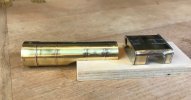
60 LRM C12 20210808 (4) buffer lining jig.jpg
61 LRM C12 20210810 (1) buffer lining 2.jpg
Various other areas followed, mainly with the compass pen following suitable edges:
64 LRM C12 20211028 (5) Cab roof lining 2.jpg
65 LRM C12 20211019 (1) Buffer beam lining 1.jpg
65a LRM C12 20210823 (2) Body so far 2.jpg
The boiler bands came next. I'd gone with the kit's brass bands - although I know a lot of people feel that brass is too thick - and whatever the pros and cons of that argument, the great advantage was the decent edge it gave for guiding the lining pen:
66 LRM C12 20211106 (10) Boiler band lining 1.jpg
Setting out the panels on the side tanks and bunker took a bit of research (and some very kind assistance from various fellow modellers - thank you again Dave, Mike, Paul and David!), in the course of which I learned of the existence of Painting Diagrams. In reading books by such people as Nigel Digby and E. F. Carter and studying lots of photos of various GNR locos, I also learned that quite different livery layouts were used on different GNR locos and that slightly different layouts were used at different times and in different paint shops on the same locos!
Eventually, I decided to print out at 4mm:1ft the best quality side view of a square-tank GNR C2 photo I could find and measure from that:
69 LRM C12 20211222 (2) Scaled photo for lining.jpg
The small pieces of brass section were laid out on ths page as they were assembled, to be used as visual guides during the lining. Ian Rathbone's book gives some excellent advice on how to plan out lining schemes and which order to do things in, including starting with the outermost lines, as they are measured in from the panel boundaries and all subsequent lines are then measured from them. I had to screw up my courage to put those first lines on though: with the chassis edges, the cab roof, the buffer housings and the boiler bands you have a guiding edge to follow: here, you have to put the pen down on a flat, empty, painted surface and keep it straight too!
70 LRM C12 20211222 (3) Side lining 1.jpg
71 LRM C12 20211230 (2) Side lining 2.jpg
73 LRM C12 20220205 3-4 (2) Double-white lining 1.jpg
74 LRM C12 20220205 3-4r (3) Double-white lining 2.jpg
The other thing I thought would be troublesome were the brushed incurved corners but once again, Ian's book has a trick (using a suitable sized washer as a guide) that helped enormously.
Actually, I found the single most useful technique in the book is that of stroking the edge of a line with a brush, just barely dampened with white spirit, in order to lift away tiny amounts of paint and thin the line, or remove bumps or imperfections. Many of the lines I did looked very poor when they first went on, but by the time I'd gone over them in that way, you wouldn't think they were the same paint! I wish I'd known that trick earlier: the only lining I'd done before this loco was on teak carriages and they would have benefited enormously from some refinement, though their short yellow lines are a lot less prominent.
After that, it was filling in the central black lines. Although some do the centre line first and then add the flanking ones, I followed Ian's book again in putting the thinner, lighter and more prominent whites on first, filling in the centre afterwards and I found that much easier.
How do I know I prefer doing it that way round? Because I'd accidentally missed out a couple of white lines and had to add them in after the black had been done: not fun!
The black was done with bow pens again and after some practice, I got fairly good at depositing sufficient black that as it settled, it nestled up against the inside edges of the bounding white lines, with removal of any overflow using my new best friend, the spirit-dampened brush:
76 LRM C12 20220223 (1) Boiler band black lining 2.jpg
79 LRM C12 20220301 (7) Bunker side white + black lining.jpg
And that pretty much brings us up to where things are at the moment. The rest of the centre black lines are now done, the bunker and side-tank edge beading has been glossed black and I'm currently doing a bit of brushing practice with the Phoenix GNR Dark Green:
LRM C12 20220326 (2) 1280x868.jpg
More photos to follow in due course...:)
 
Last edited:
Top