7mm Craxton SP

Ressaldar

Western Thunderer
The turntable has gone and I am beginning to feel better after trying to break up the concrete slab at the local household waste facility and have begun the transition of Hadlow Road SP into Craxton SP

Craxton 13.06.2022.jpg

The two cross overs, numbered 1 & 6 being the main differences to the previous layout, with a two road servicing depot (Railway Laser Lines on order) and a revised fueling area which will be fitted out with Made in Manchester items in due course.

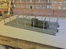
The trackwork is now in and awaiting the droppers to be fitted (locations are indicated by the 'snow pole' cocktail sticks) then the fun begins when the layout is lifted onto its side for the electrics to be installed. By retaining the core of the last layout and the fact that the point control panel was wired up for eight On - On switches already, my task should be more straight forward in that I only have to connect the crossover Tortoises under the baseboard and hopefully, all should be well.

IMG_0972.JPG
Oil tanks in the off loading siding, with the refuelling lines adjacent
IMG_0971.JPG

locos stabled in the service shed location with the furthest most 'snow poles' just in front of the entrance.

Wiring fun starts tomorrow.

regards

Mike
 

Ressaldar

Western Thunderer
I received a parcel from Railway Laser Lines on Wednesday and put it to one side without opening it as I wanted to complete the wiring before being distracted by building works. Anyway, wiring finished, tested and adjustments made ( managed to get the polarity of all four frogs on the two crossovers the wrong way round) so the box was opened.

Very well packed and parts check list enclosed, I had already printed off the instructions and had a couple of read throughs, but it is surprising how much easier it is to follow instructions when you have the parts/pieces in front of you. The base is made up of three layers with the lower two effectively trapping the trackwork in place. these lower two thicknesses were glued together and weighted down overnight. The top layer needs to be primed before fixing and to make sure that I was not held up waiting for primer to go off on subsequent pieces I checked the instructions (again) and set out all of the pieces that needed priming and did those in one go and went back later to prime the backs of those pieces that needed doing. The top layer was fixed in place and is thin enough such that when applied to the base structure, its top surface is just below railhead height without any further adjusting. This also applies to the strips between the rails. Again the base was weighted down and left for a few hours while it set.

To ensure that the roof trusses align, there are a series of laser cut holes in the various layers which enable the base to be made square and small pegs are supplied which act as a register and made life a lot easier when I placed the trusses in their slots for a dummy run.

IMG_0973.jpgIMG_0974.jpg
track ends to be trimmed back square on completion.
IMG_0976.jpg

and a trial fit of one of the residents- the slots in the bottom of the trusses are for the inner brick walls to locate and will disappear as construction proceeds.

More to come tomorrow.

regards

Mike
 

Attachments

  • IMG_0975.jpg
    IMG_0975.jpg
    141.1 KB · Views: 5

Ressaldar

Western Thunderer
A very productive day today, starting off with a couple of wash coats of Railmatch acrylic concrete to the floor areas and when dry.
IMG_0977.jpg
the roof trusses with the inner walls were fitted in place
IMG_0979.jpg
followed by the sheeting rails, temporarily held in place while the glue worked its magic
IMG_0980.jpg
followed by the external walls and then the coping flashing. Whilst this was drying, the inner rooflight frames were inserted in their apertures and left to dry off, but the urge to have a dry fit of the roof structure in place was too great and without any adjustment whatsoever, the two halves just dropped into the waiting slots.
IMG_0987.JPG
looking just as a steel frame ready for its cladding should.
IMG_0990.JPG
a really well thought out design and manufacture
IMG_0993.jpg
and again, the urge to see what it will look like when in-situ was too great. Even the 22's had a trial fit!

Meanwhile, the corrugated card cladding and roofing was primed early this morning and set aside to dry (12 hours minimum recommended) so tomorrow will see the rooflight glazing going in and then the roof structure can be fixed down, followed by the gutters being fixed and the roofing and cladding applied, which just leaves the outer rooflight frames and the end cover strips to be fixed. There are no rainwater goods included in the kit, but I have a selection of Modelu fittings in stock so I hope that I have sufficient to finish off the job, once they are painted.

I think that it would look better with a 20' concrete apron in front of the entrance so I will approach Steve to see if he can produce something.

Seem that I might be ballasting before too long!

regards

Mike
 

Al Tait

Western Thunderer
Looks ace Mike. Still waiting my primer order here but hopefully have the WRD done by next weekend. I was looking as some Modelu fittings I have in stock too!
 

Ressaldar

Western Thunderer
Hi Al,

I ran out of primer just as I finished spraying the cladding panels, so a visit to Halfords is on the cards later in the week. I have not decided on a top coat colour for the cladding, but what ever it is, it will be brush applied.

regards

Mike
 

Ressaldar

Western Thunderer
Well the cladding has been brush painted an NSEesque blue which will either receive a second coat or be overpainted with a more subtle shade of green ,
IMG_0994.JPG

as has the roof, Barley Grey
IMG_0996.JPG

and the window frames have been done in Aluminium. I think that the roof is ok, or rather will be when it receives a roof dirt wash or two and a closure piece along the ridge.

IMG_0997.JPG

all that is really left to apply are the rainwater goods to the existing box gutters and eventually, some dirt wash weathering.

I have today contacted Steve at RLL requesting that he considers doing some aprons for the front and back and he has replied that other customers have also made a similar request and he will see what can be done once he has recovered from his sick bed.

Looks like ballasting is getting ever nearer.

regards

Mike
 

Ressaldar

Western Thunderer
All done now save the weathering

IMG_0999.jpg

IMG_1001.jpg

some other would be residents trying out the facilities for size prior to the wiring up and the installation of the aprons front and back.

All in all very pleased with the kit - everything fitted, no cutting, carving, sanding or cajoling, literally, everything fell into place - oh that loco and rolling stock kits be be somewhere near the same!

regards

Mike
 

Ressaldar

Western Thunderer
This morning saw the installation of the shed onto the layout, it having been weathered with a mixture of washes - roof dirt followed by a concoction of mud brown/old rust and dark green over the course of yesterday afternoon and left to dry overnight.

IMG_1004.jpg

Having wired it into the rest of the baseboard, the 04 shunter was brought into action to test all of the trackwork, finding just one fault on one of the crossovers which was soon cured with the help of the hot stick,

Attention will now turn to the other end of the layout and the refueling point.

IMG_1006.jpg

here is the area in question and the plan is to take up the 'concrete' area, extend the left hand track (in front of the 04) to finish roughly where the white area finishes at the far end and take up/relay the right hand line to be parallel with the left hand track with a distance of 100mm between the two tracks to enable the pump island facility to go in and then relay the 'concrete' slab. Railway Laser Lines do a kit for the slabs with grillage sections and these kits may well be used.

Once this area is relaid, then the ballasting will commence.

regards

Mike
 

Ressaldar

Western Thunderer
So over the weekend, the 'concrete' area in the last photo was dug up and the tracks realigned to accept the layout of the fueling pumps and the gridwork that is on order from RLL,

IMG_1008.jpg

the line in front of the locos is the extent of the grillage and the line in front of that is the extent of the new concrete apron. The stop blocks - from chris_draw.com, are only loose fitted at present just to see that they fit.

IMG_1010.jpg

as part of the revision to the trackwork, the off loading line has been truncated to the end of the platform and again stop blocks are trial fitted, they may be replaced with a proper buffer stop. The surface of the platform had been partially removed with a view to removing it altogether but the core base (a piece of 9mm ply) had been screwed and glued into position and I decided that it would be better to keep the whole thing in-situ and therefore some remedial works need to be carried out to the end walls.
'
The fueling equipment was ordered from Made in Manchester Models' yesterday and should be here by the end of the week, in the meantime, a start will be made in ballasting the new/revised trackwork elsewhere on the layout, as well as giving thought to what goes at the foot of the boundary wall (shown at the top of the last photo) which goes the whole length of the layout and is 65mm wide to the edge of the ballast and incorporates the 'join' between the layout and the backscene which for obvious reasons, needs to be kept free of any glue.

More to come

regards

Mike

Edited to include suppliers name for the stop blocks.
 
Last edited:

Ressaldar

Western Thunderer
Wednesday morning saw the start of the ballasting something which I quite like as there is no rushing the job and with some nice music on in the background the 6mm wide flat brush soon gets the hang of what is trying to be achieved. It is Club meeting on Wednesday afternoon so had the afternoon off from ballasting and played trains for a few hours. Thursday shopping was over quite quickly so the brush was soon at work on the ballast again before lunch and again in the afternoon with the job completed around 16.00 hours. I decided to leave the gluing until this morning and that job was completed just after lunch.

Wednesday also saw the arrival of the parcel from Made in Manchester Models and I am very pleased with the contents.

IMG_1013.jpg
the two discharge pies placed in their location, the ends will be set on a concrete plinth. Hoses are provided but I will have to Fashion something to represent the coupling to the rail tank
IMG_1014.jpg
overall scene of the discharge area. I have now made up a set of steps from the 'spare parts' left over from the service shed kit to fit in the gap between the platform and the pump house. The pump house itself is made up of left overs from previous laser cut kits and fits the space just right, The jury is still out as to whether a bund wall will surround the tank base, MIMM provided a suitable piece of pipework to go up and over a bund, so it seems that a wall will be built.
IMG_1015.jpg
Discharge pump sat in the middle of what will be a concrete slab with grills fitted within the track and immediately either side - (on order from Railway Laser Lines)
IMG_1012.jpg
Overall scene of the fuel area and the keen eyed will notice the wet ballast immediately above the tank wagons and also below the van in the previous shot.

Will now leave this alone until the ballast has dried completely and wait patiently for the postie with the grills but no doubt will find enough little jobs to get on with, mainly the strip which runs the length of the layout at the foot of the boundary wall.

regards

Mike
 

Ressaldar

Western Thunderer
Hi Al,

unfortunately no, 3 boards are nominal 1200 x 600 and the final board with the service shed on is 1000 x 600. Whilst the power is individual to each board, the point control crosses the boundary as it were and goes directly from the baseboard edge to the relevant point. Also the back scene is no part of the layout as it is fixed directly to framework on the garage wall.

Will post some more progress photos later showing the grid work at the fuelling point.

regards

Mike
 

Ressaldar

Western Thunderer
another visit from the postman yesterday, this time from Railway Laser Lines and the grillage pieces for the re-fuelling area. Well thought out design, for use with Peco sleeper spacing in that the uprights supporting the central grill are castellated and fit over the sleepers and at the same time space the grillage centrally between the track to give sufficient spacing for wheel flanges

IMG_1023.jpg
here the pieces are just laid in place, having been painted to represent a 'galvanised' finish which will be weathered with fuel staining once the concrete aprons are in place.
IMG_1025.jpg
a trial run for back to back clearance with the trusty 04
IMG_1026.jpg
the concrete apron - foamboard with a plasticard overlay will extend to the black line to the left of the 04 and come up as far as the ballast on the right hand track. The infill between ballast is yet to be decided.

regards

Mike
 

Ressaldar

Western Thunderer
I should have included this photo of the centre section showing the castellation,

IMG_1027.jpg

better late than never, obviously, it only fits when the track is dead straight.

Today, I have glued the grillages in position and started to bring up the surrounding areas to be flush with the surface of the side grills, Using the nominal 5mm foamboard, there needs to be a make up of 80th - Plasticard to the fore! except for the areas immediately in front the side grills as the chairs are too high for the 80th Plasticard to slip over. Bottom and top of the following picture

IMG_1030.jpg
So these lengths of track will have a two piece make up, 60th base stopped short of the chairs and a 20th topping which will slide over the chairs and under the lip of the rail. A way of doing this using the single thickness method would be to form a 60th deep x 6mm wide rebate in the 80th Plasticard and my Proxxon drill's slowest speed is I think, too fast for such an operation and I would end up with a molten mess. The resultant surface join between the 20th topping and the 80th main slab will be 'skrawked' to give the impression of a construction joint with similar joints drawn on the remainder of the 80th slab surface.

The ends of the central grills have been completed by using two layers of 80th plasticard and will be painted 'weathered concrete' when the rest of the slab gets painted.

Clearance trials took place late this afternoon with the 04 running onto both re-fuelling lines with no problems, so it is a trip to the local model shop for supplies tomorrow morning fingers crossed that they have some 60th & 80th Plasticard id stock.

regards

Mike
 

simond

Western Thunderer
Mike,

are your grilles shy of the rail height? If not, you’ll “clean” the paint and weathering off them when giving the rails a once-over.
 

Ressaldar

Western Thunderer
Hi Simon,

Thanks for responding. Yes, they 'tuck in' just below the vertical face of the rail, granted not a lot but they are proud. I think the use of a narrow track rubber is called for.

Hope you are coping with the weather ok.

regards

Mike
 

Ressaldar

Western Thunderer
We had a thin layer of cloud all afternoon which kept the temperature down to 'bearable' but had the cool fan on in the workshop.

regards

Mike
 

Ressaldar

Western Thunderer
A trip to the local model shop for the 60thou and 80thou plasticard yesterday allowed me to continue with the topping to the concrete slab
which went better than expected, albeit that the scribing in around the stop blocks and the rebates for the backscene wall took much longer than anticipated, it was fortunate that this element was using the 20thou plasticard to bring the surface up to level and was much easier to trim.

IMG_1032.jpg

IMG_1034.jpg

and I am quite pleased with the outcome. The fuelling pump is only placed in position here as there will be a certain amount of remedial work/sanding to do before the primer and concrete surface paint is applied, as well as the construction joints. As we are shopping in the morning it means that the glue would have had at least 24 hours to go off so I should be safe with some fine sanding paper.

regards

Mike
 

Jordan

Mid-Western Thunderer
Mike how have you glued the plasticard, without it warping or melting? My attempts end in disaster with solvent glues, or end in not sticking at all with water-based glues like pva.
 
Top