You are using an out of date browser. It may not display this or other websites correctly.
You should upgrade or use an alternative browser.
You should upgrade or use an alternative browser.
Crymlyn A Shop Techniques. Barry Railway F Class.
- Thread starter davey4270
- Start date
simond
Western Thunderer
Looking at the photo in Dave’s post 59, there is a fillet radius between spokes and drilled balance weight, but not on the “new” weight. The fillet suggests to me that the drilled weight was cast integrally with the spokes, and the new weight was an add-on
I doubt that anyone would be in a tearing hurry to weld the weights on, my cursory knowledge of metallurgy suggests that is likely to end in tears (whichever way you say it) so I would expect the new weights to be riveted, or screwed & riveted like a boiler stay. The fronts of the weights are very close to the backs of the rods, so flush riveting would seem necessary. The back is probably less tight for clearance, but much less likely to figure in anyone’s photo collection.
if it was relatively common, presumably on absorbed locos, I guess that there must have been a plan/budget/drawing office instruction somewhere.
Atb
Simon
davey4270
Western Thunderer
I have had a reply from Alan Kirkman on a Facebook site and according to the RCTS books, which I don't have, Swindon changed the Crank Axles to Swindon style built up ones (with some balance built in) rather than one piece solid forged ones so that meant rebalancing the axle and wheel assembly, drilling holes in some original cast in weights and adding new externally.I have plenty of photos but no explanation although Adrian's would seem a good possibility.
View attachment 140804
Dave
Thank you Alan for this information.
davey4270
Western Thunderer
130. A Start on the Wheels.

I drew a few circles on black Plasticard the size of the wheels and carefully cut them out. I drew a second circle 3mm smaller and also cut this out leaving a ring of black plastic the size of the balance weights just needing to be trimmed to the number of spokes required for each weight. I chose black as there was less chance of any colour showing through if they got scuffed. I then cut each weight to the relevant number of spokes as per the prototype pictures and superglued them in position.
After allowing plenty of time for them to dry, I drilled the modified weights on the centre wheels from the back with a 2.1mm bit in each corner next to the spokes which will give that sideways figure 8 effect of the Swindon modification to the balancing. The intention being to mark where the Milliput will be drilled from the outside hopefully making the outside neat and any unevenness less visible on the inside. I mixed up some Milliput and squashed it into the spaces on each wheel between the spokes which will, hopefully, give the impression of a cast weight.
The picture shows where the Milliput has squeezed through the holes and will be further cleaned up before it sets.
davey4270
Western Thunderer
130. Bits and Pieces.
Progress is slow at the moment mainly due to a shortage of components.

The spare shaft on the Taff Vale Models motor was cut off with a slitting disc in a mini drill. This was necessary to give adequate clearance in the firebox. With most saddle tanks the tank reaches the cab front so the top of the firebox doesn’t need to be modelled. The end of the motor to be cut was covered in masking tape to prevent any ingress of metal dust and the shaft slowly cut with the slitting disc. Great heat will be generated here which could soften the plastic holding the bearings so take care and allow the job to cool half way through and WEAR EYE PROTECTION! This will now give extra height for clearance of the motor. The picture shows the motor which was previously mounted on a reconditioned gearbox with the excess shaft removed.

The wheels have had their balance weights fitted and painted. The L/H wheels are for the leading axle and have that strange extra small balance weight. A black plasticard front was superglued to the wheels and Milliput used to fill the rear to represent solid weights cast with the wheels.
The R/H wheels for the trailing axle were treated identically. These 4 wheels have had 2 coats of paint.
The centre pair for the driven axle have had the original cast weights (at 6 o’clock to 9 o’clock) made up in the same way and drilled out twice between each spoke with a 2.2mm drill. Apparently this was done at Swindon to rebalance a replacement crank axle of a different type. A new balance weight was added (at 2 o’clock to 6 o’clock) as per the prototype. These 2 wheels will have a second coat of paint.

Unfortunately a shortage of handrail knobs has caused a delay with the body as I like to solder them from the inside. I have some “long” knobs,
 I’m not changing it
, and attempting to align the handrail wire with them resulted in it being pushed out. I’ll have to get around to ordering some.
I’m not changing it
, and attempting to align the handrail wire with them resulted in it being pushed out. I’ll have to get around to ordering some.
Progress is slow at the moment mainly due to a shortage of components.
The spare shaft on the Taff Vale Models motor was cut off with a slitting disc in a mini drill. This was necessary to give adequate clearance in the firebox. With most saddle tanks the tank reaches the cab front so the top of the firebox doesn’t need to be modelled. The end of the motor to be cut was covered in masking tape to prevent any ingress of metal dust and the shaft slowly cut with the slitting disc. Great heat will be generated here which could soften the plastic holding the bearings so take care and allow the job to cool half way through and WEAR EYE PROTECTION! This will now give extra height for clearance of the motor. The picture shows the motor which was previously mounted on a reconditioned gearbox with the excess shaft removed.
The wheels have had their balance weights fitted and painted. The L/H wheels are for the leading axle and have that strange extra small balance weight. A black plasticard front was superglued to the wheels and Milliput used to fill the rear to represent solid weights cast with the wheels.
The R/H wheels for the trailing axle were treated identically. These 4 wheels have had 2 coats of paint.
The centre pair for the driven axle have had the original cast weights (at 6 o’clock to 9 o’clock) made up in the same way and drilled out twice between each spoke with a 2.2mm drill. Apparently this was done at Swindon to rebalance a replacement crank axle of a different type. A new balance weight was added (at 2 o’clock to 6 o’clock) as per the prototype. These 2 wheels will have a second coat of paint.
Unfortunately a shortage of handrail knobs has caused a delay with the body as I like to solder them from the inside. I have some “long” knobs,
davey4270
Western Thunderer
131. Fitting the Motor.

A couple of jobs completed today included fitting the motor, trailing wheels and axle. I needed to cut out the rear top brake hanger between the frames to clear the gearbox, an easy job with a pair of side cutters. I left a 2mm stub inside the frames to leave some support for the hangers as they are soldered from inside. A small flat was filed near the centre of the axle for the gear wheel grub screw to locate. I arranged this to that it was inline with the R/H trailing wheel crank pin so that the flat could be located when I was ready to tighten it. Two 0.55mm shims from a Slater’s etching were cleaned up and fitted either side between the bearings and the wheels which left some perceptible play. A quick test with power directly to the motor proved that everything ran sweetly. There is very little play between the gearbox bearings and the gear wheel so the motor will not be sliding about which is desirable.
The front wheel set was also fitted and the centre, driven wheels have had a second coat of paint.
The motor is running in the picture hence the blurry gear wheel.

Elsewhere, a new supplier has been sourced for handrail knobs. Amberley Services will hopefully supply these for the weekend. A pencil line was drawn along either side of the tank level with the handrail location on the cab front and parallel to the footplate. The positions of the handrail knobs on the prototype 726 were identified and transferred to the model. I marked where the holes would be drilled with a needle approximately 1mm lower than the pencil mark as the shape of the tank will angle the handrail knobs upwards. I will double check this, when the handrail knobs arrive, before drilling.
A couple of jobs completed today included fitting the motor, trailing wheels and axle. I needed to cut out the rear top brake hanger between the frames to clear the gearbox, an easy job with a pair of side cutters. I left a 2mm stub inside the frames to leave some support for the hangers as they are soldered from inside. A small flat was filed near the centre of the axle for the gear wheel grub screw to locate. I arranged this to that it was inline with the R/H trailing wheel crank pin so that the flat could be located when I was ready to tighten it. Two 0.55mm shims from a Slater’s etching were cleaned up and fitted either side between the bearings and the wheels which left some perceptible play. A quick test with power directly to the motor proved that everything ran sweetly. There is very little play between the gearbox bearings and the gear wheel so the motor will not be sliding about which is desirable.
The front wheel set was also fitted and the centre, driven wheels have had a second coat of paint.
The motor is running in the picture hence the blurry gear wheel.
Elsewhere, a new supplier has been sourced for handrail knobs. Amberley Services will hopefully supply these for the weekend. A pencil line was drawn along either side of the tank level with the handrail location on the cab front and parallel to the footplate. The positions of the handrail knobs on the prototype 726 were identified and transferred to the model. I marked where the holes would be drilled with a needle approximately 1mm lower than the pencil mark as the shape of the tank will angle the handrail knobs upwards. I will double check this, when the handrail knobs arrive, before drilling.
davey4270
Western Thunderer
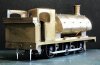
132. Attaching the Tank.

Something that was slowing progress was my shortage of handrail knobs. A new supplier was identified, Amberley Services, who won the contract. I prefer to solder the handrail knobs from the inside as this is much neater. A problem was encountered with the overlay plates on the tank giving uneven levels to obtain a straight run the handrail wire. The wire extends past the rear of the tank, across the firebox and into the front of the cab. This was resolved by heating the solder inside the tank on the offending handrail knobs and gently easing them out. The 4 etched holes for the handrail knobs around the tank filler at the top rear of the tank were too large to accurately locate the spigots but, fortunately, not too big for the knobs to pass through. Some care was needed to accurately align these while soldering. A few blemishes were treated with Milliput resin putty and sanded smooth.

With that job complete, the tank could now be permanently attached to the boiler. The tank front was aligned with the smoke box front and, after applying flux to the 6 tank support brackets, firmly pressed against them. A rear bracket and the opposite front bracket were tack soldered and everything rechecked for alignment. Once happy, all the support brackets were soldered to the underneath of the tank and also the tab on the rear tank former was soldered from the inside to the top of the firebox. The other tank former tabs are now inaccessible so were left.
The picture shows the tank support brackets and the strip of brass angle running along the base of the firebox sides. One of the captive nuts is also just visible inside the rear of the firebox as are the holes for the front fixing screws to pass through.

A view of the top of the completed tank/boiler assembly. Some more attention with Milliput will be required at the front and rear of the tank against the boiler. The assembly easily slips in and out of the footplate which will make painting much easier.
Something that was slowing progress was my shortage of handrail knobs. A new supplier was identified, Amberley Services, who won the contract. I prefer to solder the handrail knobs from the inside as this is much neater. A problem was encountered with the overlay plates on the tank giving uneven levels to obtain a straight run the handrail wire. The wire extends past the rear of the tank, across the firebox and into the front of the cab. This was resolved by heating the solder inside the tank on the offending handrail knobs and gently easing them out. The 4 etched holes for the handrail knobs around the tank filler at the top rear of the tank were too large to accurately locate the spigots but, fortunately, not too big for the knobs to pass through. Some care was needed to accurately align these while soldering. A few blemishes were treated with Milliput resin putty and sanded smooth.
With that job complete, the tank could now be permanently attached to the boiler. The tank front was aligned with the smoke box front and, after applying flux to the 6 tank support brackets, firmly pressed against them. A rear bracket and the opposite front bracket were tack soldered and everything rechecked for alignment. Once happy, all the support brackets were soldered to the underneath of the tank and also the tab on the rear tank former was soldered from the inside to the top of the firebox. The other tank former tabs are now inaccessible so were left.
The picture shows the tank support brackets and the strip of brass angle running along the base of the firebox sides. One of the captive nuts is also just visible inside the rear of the firebox as are the holes for the front fixing screws to pass through.
A view of the top of the completed tank/boiler assembly. Some more attention with Milliput will be required at the front and rear of the tank against the boiler. The assembly easily slips in and out of the footplate which will make painting much easier.
davey4270
Western Thunderer
133. More on the Tank.

After days of trying to remove the wrinkles from the Bacofoil thin front tank former, I bit the bullet and buried the lot under Milliput. The front tank former was half etched giving some rivet detail which didn’t match any prototype pictures that I have. The etched rivets were too big, there weren’t nearly enough of them and the inner row followed the curvature of the smoke box below its widest point instead of dropping down vertically. There was a small cosmetic infill piece to cover the gap on the prototype giving this illusion. There isn’t much detail on the tank/smoke box front but when I place the smoke box door in position, it makes a tremendous difference. The addition of a couple of handrail knobs, the handrail wire, the smoke box door dart, a steam lance cock, lamp irons and the chimney which will draw your eyes away from the front will make all the difference.

A view from the front showing the balance pipe fitted in the previously attached flanges. This was made from a piece of 1.6mm nickel silver wire, which was the largest I had, and soldered in place.
The front of the tank does look flat and so it would having been being sanded flat with a piece of emery on plate glass. As mentioned in the previous caption, hopefully the front detail will alleviate this. Buffers, a 3 link coupling and a front lamp will also give additional detail. I cannot make out buffer plank numbers in my pictures and I have a suspicion that these were not regularly applied to absorbed locomotives, the GWR cast in the cab side plate sufficing. I have seen pictures of some absorbed locomotives with them but not Barry F’s. Perhaps some works applied them and not others.
As an aside, I’ve had this piece of plate glass for about 40 years and have lost count of the number of chassis that have been constructed on it! This model only just fitted on it so unless I acquire a larger piece, this will be the largest model I’ll build.

A rear 3/4 view showing the tank rear sitting snugly on the firebox. Some Milliput was applied here to make a flush finish to the rear of the tank. The motor is in position, but obviously not visible, and the top of the firebox is sufficiently clear of it. The balance pipe is again visible as are the “frames” between the splashers.
With the boiler/firebox removed and power leads clipped to the motor terminals, the chassis/footplate/cab assembly ran smoothly over a foot of my test track. I say a foot as this was limited by the length of the power leads.
After days of trying to remove the wrinkles from the Bacofoil thin front tank former, I bit the bullet and buried the lot under Milliput. The front tank former was half etched giving some rivet detail which didn’t match any prototype pictures that I have. The etched rivets were too big, there weren’t nearly enough of them and the inner row followed the curvature of the smoke box below its widest point instead of dropping down vertically. There was a small cosmetic infill piece to cover the gap on the prototype giving this illusion. There isn’t much detail on the tank/smoke box front but when I place the smoke box door in position, it makes a tremendous difference. The addition of a couple of handrail knobs, the handrail wire, the smoke box door dart, a steam lance cock, lamp irons and the chimney which will draw your eyes away from the front will make all the difference.
A view from the front showing the balance pipe fitted in the previously attached flanges. This was made from a piece of 1.6mm nickel silver wire, which was the largest I had, and soldered in place.
The front of the tank does look flat and so it would having been being sanded flat with a piece of emery on plate glass. As mentioned in the previous caption, hopefully the front detail will alleviate this. Buffers, a 3 link coupling and a front lamp will also give additional detail. I cannot make out buffer plank numbers in my pictures and I have a suspicion that these were not regularly applied to absorbed locomotives, the GWR cast in the cab side plate sufficing. I have seen pictures of some absorbed locomotives with them but not Barry F’s. Perhaps some works applied them and not others.
As an aside, I’ve had this piece of plate glass for about 40 years and have lost count of the number of chassis that have been constructed on it! This model only just fitted on it so unless I acquire a larger piece, this will be the largest model I’ll build.
A rear 3/4 view showing the tank rear sitting snugly on the firebox. Some Milliput was applied here to make a flush finish to the rear of the tank. The motor is in position, but obviously not visible, and the top of the firebox is sufficiently clear of it. The balance pipe is again visible as are the “frames” between the splashers.
With the boiler/firebox removed and power leads clipped to the motor terminals, the chassis/footplate/cab assembly ran smoothly over a foot of my test track. I say a foot as this was limited by the length of the power leads.
davey4270
Western Thunderer
134 Chimneys and Doors.

The smoke box door supplied is a white metal casting and after some cleaning up, actually it wasn’t too bad, looked like a fair representation of the prototype. Both surfaces were given a good clean and it was fixed in place with Araldite Rapid. This gives a few minutes to make minor adjustments before it goes off. I used a rule laid across the footplate in front the smoke box to check that the door hinges were horizontal. The model was upended onto its bunker to that the door was horizontal and wouldn’t move while the Araldite went off. The trick here is to give it 10 minutes and carefully cut through the excess Araldite that has squeezed out with a sharp knife before it sets hard. Most of the excess can then be peeled away like chewing gum.
A similar method was used to affix the chimney, which was a brass turning, making sure it was vertical in all planes before the glue went off. The locomotive standing on its wheels in this case.

Another 3/4 view. No excuses here, I just like the look of the locomotive from this angle.
The smoke box door supplied is a white metal casting and after some cleaning up, actually it wasn’t too bad, looked like a fair representation of the prototype. Both surfaces were given a good clean and it was fixed in place with Araldite Rapid. This gives a few minutes to make minor adjustments before it goes off. I used a rule laid across the footplate in front the smoke box to check that the door hinges were horizontal. The model was upended onto its bunker to that the door was horizontal and wouldn’t move while the Araldite went off. The trick here is to give it 10 minutes and carefully cut through the excess Araldite that has squeezed out with a sharp knife before it sets hard. Most of the excess can then be peeled away like chewing gum.
A similar method was used to affix the chimney, which was a brass turning, making sure it was vertical in all planes before the glue went off. The locomotive standing on its wheels in this case.
Another 3/4 view. No excuses here, I just like the look of the locomotive from this angle.
davey4270
Western Thunderer
135. Buffers and Domes.
I found an old set of buffers in the back of my toolbox marked B1122 GWR Dean Churchward although nobody is claiming ownership. They are turned brass and differ from the Dean type I am familiar with. I hasten to add that I am by no stretch of the imagination an expert on buffers but do look like a type fitted to some of the F class locomotives in pictures that I have. The spigots on the buffer housings were significantly bigger than the etched holes provided on the buffer planks so they were opened up with a taper reamer to accommodate them. The reamer removes material equally around the holes keeping the hole centres relative to each other. I placed a smear of flux under the base of the buffer housings and aligned them with a steel rule across the bottom of the two flanges to ensure they were straight. A spot of solder on the inside and my 40W iron ensured the solder spread through the buffer plank and underneath the housing base flange.
The picture shows a before and after hole.

The dome was attached in my usual manner with Araldite. A few rivets needed to be removed from the etched tank overlay to allow the dome to sit flat on the tank. The dome supplied was of turned brass with a tapped thread underneath, although how one could secure it with a screw is beyond me especially as there is now no access to the inside of the tank!
The picture, again taken from my favourite rear 3/4 angle, shows the buffers and dome in position. I have also placed the cab rear sheet and roof in position to better illustrate the model.
I found an old set of buffers in the back of my toolbox marked B1122 GWR Dean Churchward although nobody is claiming ownership. They are turned brass and differ from the Dean type I am familiar with. I hasten to add that I am by no stretch of the imagination an expert on buffers but do look like a type fitted to some of the F class locomotives in pictures that I have. The spigots on the buffer housings were significantly bigger than the etched holes provided on the buffer planks so they were opened up with a taper reamer to accommodate them. The reamer removes material equally around the holes keeping the hole centres relative to each other. I placed a smear of flux under the base of the buffer housings and aligned them with a steel rule across the bottom of the two flanges to ensure they were straight. A spot of solder on the inside and my 40W iron ensured the solder spread through the buffer plank and underneath the housing base flange.
The picture shows a before and after hole.
The dome was attached in my usual manner with Araldite. A few rivets needed to be removed from the etched tank overlay to allow the dome to sit flat on the tank. The dome supplied was of turned brass with a tapped thread underneath, although how one could secure it with a screw is beyond me especially as there is now no access to the inside of the tank!
The picture, again taken from my favourite rear 3/4 angle, shows the buffers and dome in position. I have also placed the cab rear sheet and roof in position to better illustrate the model.
Attachments
davey4270
Western Thunderer
136. Tank Fillers and Sandboxes.

A new contract has been negotiated with Gladiator Models who supply a kit for a Barry A Class. These are similar locomotives but look incredibly different with the tank arrangements. The A class has side tanks while the F class has a shortened saddle tank forward mounted. I wonder if this was to improve balance and weight distribution? Anyway, the fittings appear almost identical and David Hill of Railway City Trains Ltd agreed to supply me with the missing fittings at a very reasonable cost. He was unable to supply me with an etched floor, quite understandably, as it would have destroyed one of his etches making it unsellable. He did, however, supply me with a photograph and measurements of the required etch so I could make one. I plan to do this with a piece of card to check the fit before cutting one out in brass. David also supplied a detailed drawing of the back head to enable me to add the detailed fittings. The Barry Railway condition appears to have a pair of injector/ clack valves on the back head but many pictures show, mainly on the R/H side only, a GWR type fitted. Would they have replaced only one feeding through a new firebox clack valve? Any suggestions would be welcome.
A cast lift off tank filler was provided with the kit which matched the fitting on the earlier Barry Rly condition but my chosen prototype, 726, has a clamp type. I was fortunate in having a suitable spare I hadn’t used supplied by Andrew Beaton which was suitable and this was Araldited in place along with the first of the castings from Gladiator Models, the front sandboxes. Also placed in position for the photograph is the GWR type safety valve bonnet and boiler mount.
john lewsey
Western Thunderer
That loco is looking very nice
John
John
Last edited:
davey4270
Western Thunderer
Thank you John.That loco is looking vert nice
John
davey4270
Western Thunderer
137. Front Sand pipes and Pick Up Pads.

The first job of the day was to Araldite the previously assembled safety valve bonnet in place. Typically of this locomotive, this is not mounted central in the space between the tank and the cab front but centrally over the entire firebox including the part under the tank and the part inside the cab. Fortunately there is an etched boiler band in the actual centre of the firebox which indicates this. Unfortunately the central part of it needs removing to allow the safety valve bonnet to sit flush. A few minutes work with a flat file soon sorted this and, even though it sits nearer the tank, it is correctly positioned.
There are 2 small holes in the footplate above the sandboxes to locate the filler lids. The parts I received from Railway City Trains looked too large for what , basically, were lift off covers so I substituted 2 discs of 30 thou Plasticard cut in a paper punch. These were superglued in place with 00 track pins as handles. The excess pins underneath being cut off and filed flat to clear the cast sandboxes.

Some 0.9mm brass wire was bent to the appropriate shape of the prototype’s sand pipes and superglued in a suitable hole drilled from underneath the sandboxes. A 16 BA washer was added to represent the flange.
I estimated where the paxolin (copper clad) pads for the pickups on the first and second wheels would go and cut out “notches” in the top of the frames. Unfortunately the second pair are partly covered by the firebox wrapper extending beneath the footplate, this will need to be trimmed to clear the pick up mounting pad before it can be fitted. A point to be careful of here is that these don’t touch the footplate as it could prevent the body from sitting correctly. I aware of this when fitting the front sandboxes so I placed a card spacer between the top of the sandboxes and the footplate. The card was removed when the glue had set.
The picture shows the sand pipes and the pick up pad notches in the frames with the second notch being partially covered by the firebox wrapper.
The first job of the day was to Araldite the previously assembled safety valve bonnet in place. Typically of this locomotive, this is not mounted central in the space between the tank and the cab front but centrally over the entire firebox including the part under the tank and the part inside the cab. Fortunately there is an etched boiler band in the actual centre of the firebox which indicates this. Unfortunately the central part of it needs removing to allow the safety valve bonnet to sit flush. A few minutes work with a flat file soon sorted this and, even though it sits nearer the tank, it is correctly positioned.
There are 2 small holes in the footplate above the sandboxes to locate the filler lids. The parts I received from Railway City Trains looked too large for what , basically, were lift off covers so I substituted 2 discs of 30 thou Plasticard cut in a paper punch. These were superglued in place with 00 track pins as handles. The excess pins underneath being cut off and filed flat to clear the cast sandboxes.
Some 0.9mm brass wire was bent to the appropriate shape of the prototype’s sand pipes and superglued in a suitable hole drilled from underneath the sandboxes. A 16 BA washer was added to represent the flange.
I estimated where the paxolin (copper clad) pads for the pickups on the first and second wheels would go and cut out “notches” in the top of the frames. Unfortunately the second pair are partly covered by the firebox wrapper extending beneath the footplate, this will need to be trimmed to clear the pick up mounting pad before it can be fitted. A point to be careful of here is that these don’t touch the footplate as it could prevent the body from sitting correctly. I aware of this when fitting the front sandboxes so I placed a card spacer between the top of the sandboxes and the footplate. The card was removed when the glue had set.
The picture shows the sand pipes and the pick up pad notches in the frames with the second notch being partially covered by the firebox wrapper.
Last edited:
daifly
Western Thunderer
DavidThe picture shows the sand pipes and the pick up pad notches in the frames with the second notch being partially covered by the firebox wrapper.
Unfortunately, you posted this interesting picture as a thumbnail, not full-size!
Dave
davey4270
Western Thunderer
Thank you David, hopefully sorted.David
Unfortunately, you posted this interesting picture as a thumbnail, not full-size!
Dave
davey4270
Western Thunderer
137a. More on the Pickups.
.jpg")
I had some concerns about fitting the copper clad pads for the rear wheel pickups when locating them underneath the cab with the rear chassis locating screws and the sand pipes. However, I needn’t have worried as the chassis spacer was low enough to accommodate the copper clad across the frames and the locating screw was far enough towards the rear to clear it.
I stripped the chassis down to keep the components safe while I abused the chassis with a flat needle file to clear slots for the copper clad. These can be seen in the picture with the rear of the chassis to the left. The horn blocks can also be seen held in place with temporary staples which, unfortunately, are hidden beneath the axle boxes.

The stripped down frames are seen in place with the part built body.
I had some concerns about fitting the copper clad pads for the rear wheel pickups when locating them underneath the cab with the rear chassis locating screws and the sand pipes. However, I needn’t have worried as the chassis spacer was low enough to accommodate the copper clad across the frames and the locating screw was far enough towards the rear to clear it.
I stripped the chassis down to keep the components safe while I abused the chassis with a flat needle file to clear slots for the copper clad. These can be seen in the picture with the rear of the chassis to the left. The horn blocks can also be seen held in place with temporary staples which, unfortunately, are hidden beneath the axle boxes.
The stripped down frames are seen in place with the part built body.
davey4270
Western Thunderer
138. Pickups and Lamp irons.

The 3 pickup mounts have been soldered in place on the frames. The lower part of the firebox where it protrudes beneath the frames has had a slot filed out of it to clear the central pick up pad. This was easier than I thought and I managed to do it without dismantling the body. There was sufficient access to do this with a flat needle file leaving the removed portion flush with the underneath of the footplate.
I will have to work out a way of mounting the rear sand pipes to keep clear of the rear pickups. They will be held in position by passing them through a split pin which will be fitted through a hole drilled through the frames at roughly mid point and soldered. On this particular locomotive the sandboxes were fitted in the cab with just the pipes below the footplate and I will need to arrange the top part to clear the pick up wires. Some of the class had sandboxes mounted below the footplate the same as at the front. This would have been an even bigger challenge.

A view of the inverted frames. When I soldered the copper clad in place, I positioned a piece of card to pack up, or rather down, slightly so that the copper clad was just below the top of the frames. This was to ensure that the body will sit on the frames without being misaligned by the copper clad sitting too high.
I have replaced the rear wheels to help with aligning the rear sand pipes.

I cut out a piece of card to the A class etched floor dimensions that David Hill of “Railway City Trains” sent me and it is a perfect fit. This meant that I could position the cab rear up against the rear cab beading knowing that the floor will just drop in. But before this I noticed that there would be limited access to the bottom of the bunker sheet from inside making soldering the rear lamp irons difficult. I fitted the lower 3 lamp irons using Laurie Griffin castings and soldering from the inside meaning zero outside cleaning up. I won’t worry about the inside as it’ll be buried under a couple of tons of coal! As an aside, old railway firemen friends have told me similar stories of enormous lumps of coal blocking the coal shovelling hole on tank engines. There was no access from above with several tons of coal burying it so the only solution was with a coal pick and try to break it up from inside. Not the easiest of tasks on the move. After a couple of solder tacks in each corner, the alignment was ok and the seams were securely soldered.
The next job will be to scratch build the floor in brass from my template and scribe the planks for the floorboards.
The 3 pickup mounts have been soldered in place on the frames. The lower part of the firebox where it protrudes beneath the frames has had a slot filed out of it to clear the central pick up pad. This was easier than I thought and I managed to do it without dismantling the body. There was sufficient access to do this with a flat needle file leaving the removed portion flush with the underneath of the footplate.
I will have to work out a way of mounting the rear sand pipes to keep clear of the rear pickups. They will be held in position by passing them through a split pin which will be fitted through a hole drilled through the frames at roughly mid point and soldered. On this particular locomotive the sandboxes were fitted in the cab with just the pipes below the footplate and I will need to arrange the top part to clear the pick up wires. Some of the class had sandboxes mounted below the footplate the same as at the front. This would have been an even bigger challenge.
A view of the inverted frames. When I soldered the copper clad in place, I positioned a piece of card to pack up, or rather down, slightly so that the copper clad was just below the top of the frames. This was to ensure that the body will sit on the frames without being misaligned by the copper clad sitting too high.
I have replaced the rear wheels to help with aligning the rear sand pipes.
I cut out a piece of card to the A class etched floor dimensions that David Hill of “Railway City Trains” sent me and it is a perfect fit. This meant that I could position the cab rear up against the rear cab beading knowing that the floor will just drop in. But before this I noticed that there would be limited access to the bottom of the bunker sheet from inside making soldering the rear lamp irons difficult. I fitted the lower 3 lamp irons using Laurie Griffin castings and soldering from the inside meaning zero outside cleaning up. I won’t worry about the inside as it’ll be buried under a couple of tons of coal! As an aside, old railway firemen friends have told me similar stories of enormous lumps of coal blocking the coal shovelling hole on tank engines. There was no access from above with several tons of coal burying it so the only solution was with a coal pick and try to break it up from inside. Not the easiest of tasks on the move. After a couple of solder tacks in each corner, the alignment was ok and the seams were securely soldered.
The next job will be to scratch build the floor in brass from my template and scribe the planks for the floorboards.
davey4270
Western Thunderer
139. A Quick scratch in the Cab.

I transferred the measurements of the card floor mock up onto a piece of brass, thank you Dave Latham, and cut it out. An extra 3mm has been allowed each side to fold down and raise the floor. Lines were scored underneath at these points to allow the sides to fold down. On a half etched part there would be etched fold lines but I replicated this with several strokes (10) from my Olfa cutter. The component was then turned over and the planks were inscribed in a similar manner using a steel rule at 4mm spaces. After a clean up with some emery paper the sides were bent down and after some tweaking, to square it all up, it was dropped in place in the cab. It doesn’t sit quite flush against the cab rear but this is due to excess solder in the corners that needs clearing. I will also have to drill a hole for the handbrake standard which would have been mounted on the lower floor passing through the raised “wood” floor. I will have to estimate its position from the chassis handbrake connection but it will be forward of the cab doors on the left. The hole for its position is visible in the picture of the etch I was sent but I couldn’t accurately transpose this so will estimate it.

A study of my scale drawing showed the firebox back head to protrude several millimetres into the cab. The casting kindly supplied David Hall wasn’t deep or high enough to match the drawing and, having no experience of the Gladiator A Class kit they came from, decided the easiest way was to make a wrapper (lagging cover) and solder it to the cast back head. Of course this may be supplied with the kit but a 6mm wide strip of brass was cut 90mm long and rolled to shape. This was given a “stain” of 145’ solder to allow the low melt to adhere (it won’t take to brass, only to solder) and low melt soldered in place overlapping about half way onto the casting. I manage this without any temperature controlled irons, simply applying some low melt flux to the joint, place a small lump of low melt solder against the joint and heat the brass close by with my Antex 25W iron. As it warms the solder will melt and run into the joint. Allow to cool and the job’s done, when the solder is molten it is shiny but turns dull when it sets. Take your time as this will be longer than you think.
The picture shows the casting sitting on the wood floor. I’ll add a few brass wire “pegs” to clip it in place.
When I said “a quick scratch in the cab” you knew that I was talking about scratch building didn’t you?
I transferred the measurements of the card floor mock up onto a piece of brass, thank you Dave Latham, and cut it out. An extra 3mm has been allowed each side to fold down and raise the floor. Lines were scored underneath at these points to allow the sides to fold down. On a half etched part there would be etched fold lines but I replicated this with several strokes (10) from my Olfa cutter. The component was then turned over and the planks were inscribed in a similar manner using a steel rule at 4mm spaces. After a clean up with some emery paper the sides were bent down and after some tweaking, to square it all up, it was dropped in place in the cab. It doesn’t sit quite flush against the cab rear but this is due to excess solder in the corners that needs clearing. I will also have to drill a hole for the handbrake standard which would have been mounted on the lower floor passing through the raised “wood” floor. I will have to estimate its position from the chassis handbrake connection but it will be forward of the cab doors on the left. The hole for its position is visible in the picture of the etch I was sent but I couldn’t accurately transpose this so will estimate it.
A study of my scale drawing showed the firebox back head to protrude several millimetres into the cab. The casting kindly supplied David Hall wasn’t deep or high enough to match the drawing and, having no experience of the Gladiator A Class kit they came from, decided the easiest way was to make a wrapper (lagging cover) and solder it to the cast back head. Of course this may be supplied with the kit but a 6mm wide strip of brass was cut 90mm long and rolled to shape. This was given a “stain” of 145’ solder to allow the low melt to adhere (it won’t take to brass, only to solder) and low melt soldered in place overlapping about half way onto the casting. I manage this without any temperature controlled irons, simply applying some low melt flux to the joint, place a small lump of low melt solder against the joint and heat the brass close by with my Antex 25W iron. As it warms the solder will melt and run into the joint. Allow to cool and the job’s done, when the solder is molten it is shiny but turns dull when it sets. Take your time as this will be longer than you think.
The picture shows the casting sitting on the wood floor. I’ll add a few brass wire “pegs” to clip it in place.
When I said “a quick scratch in the cab” you knew that I was talking about scratch building didn’t you?
davey4270
Western Thunderer
139a. Another Scratch in the Cab.
.JPEG")
A few examples of the differences between the various members of the class. Here we have 715 fitted with combined injections and clack valves on the backhead. A rod runs from the cab front to the water shut off valve at the base of the tank and a water feed pipe running from the valve into the cab to the injector feed.
The reverser reach rod is at a steep angle from the cab to the reverser linkage just behind the grab handle above the front step.
.jpg")
Here we have my chosen prototype 726. It is fitted with GWR pattern injectors and the multitude of pipes are, hopefully, from top to bottom: a small pipe running to the smoke box (lubrication or possibly blower), a rod to operate the water shut off valve, feed water outlet to the backhead mounted clack valve and the live steam supply which curves up over the outlet to enter the injector above the water inlet at the bottom of the injector. Note the low reverser reach rod passing behind the water valve operating rod confuses the issue.

The etched reverser reach rod was a tad puny so I made a replacement. This needed to be wider and longer. The original is lying in position on the footplate valance and is clearly too short as well as a bit feeble. A slot was cut in the cab front by drilling several holes and joining them up with a suitable needle file to allow the reverser reach rod to pass through. The link to the mechanism at the front was held in position with Blutac while the reach rod was secured to it with a piece of 1.2mm brass rod and the joint soldered. This will be removed for fitting after painting.

I estimated the position of the hand brake pillar from rather vague cab pictures and the link to the brake cross bar and drilled a small hole through the new raised cab floor continuing through the original floor. The lower hole was enlarged to suit a spare hand brake casting’s spigot from an older kit and the hole in the raised floor was further enlarged to suit the wider body of the hand brake column. The brake column would have been mounted onto steelwork and the wooden floor boards would have been cut around this.
The tail of the reverser reach rod can be seen entering the cab close to the firebox, it’ll need shortening, and a casting supplied by David Hall is lying near it. The casting’s reach rod will need to be aligned to the new brass reach rod. I don’t think I’ll need to be too precise here as it’ll be out of sight in the gloom of the cab.
I can work out the injector feed to the backhead clacks but where would their live steam supply come from? As built it had a combined live steam/clack valve/injector casting but when this was removed for new clacks from the GWR style injectors where did the live steam supply come from? Did they fit a steam fountain as well? Any help would be welcome.
A few examples of the differences between the various members of the class. Here we have 715 fitted with combined injections and clack valves on the backhead. A rod runs from the cab front to the water shut off valve at the base of the tank and a water feed pipe running from the valve into the cab to the injector feed.
The reverser reach rod is at a steep angle from the cab to the reverser linkage just behind the grab handle above the front step.
Here we have my chosen prototype 726. It is fitted with GWR pattern injectors and the multitude of pipes are, hopefully, from top to bottom: a small pipe running to the smoke box (lubrication or possibly blower), a rod to operate the water shut off valve, feed water outlet to the backhead mounted clack valve and the live steam supply which curves up over the outlet to enter the injector above the water inlet at the bottom of the injector. Note the low reverser reach rod passing behind the water valve operating rod confuses the issue.
The etched reverser reach rod was a tad puny so I made a replacement. This needed to be wider and longer. The original is lying in position on the footplate valance and is clearly too short as well as a bit feeble. A slot was cut in the cab front by drilling several holes and joining them up with a suitable needle file to allow the reverser reach rod to pass through. The link to the mechanism at the front was held in position with Blutac while the reach rod was secured to it with a piece of 1.2mm brass rod and the joint soldered. This will be removed for fitting after painting.
I estimated the position of the hand brake pillar from rather vague cab pictures and the link to the brake cross bar and drilled a small hole through the new raised cab floor continuing through the original floor. The lower hole was enlarged to suit a spare hand brake casting’s spigot from an older kit and the hole in the raised floor was further enlarged to suit the wider body of the hand brake column. The brake column would have been mounted onto steelwork and the wooden floor boards would have been cut around this.
The tail of the reverser reach rod can be seen entering the cab close to the firebox, it’ll need shortening, and a casting supplied by David Hall is lying near it. The casting’s reach rod will need to be aligned to the new brass reach rod. I don’t think I’ll need to be too precise here as it’ll be out of sight in the gloom of the cab.
I can work out the injector feed to the backhead clacks but where would their live steam supply come from? As built it had a combined live steam/clack valve/injector casting but when this was removed for new clacks from the GWR style injectors where did the live steam supply come from? Did they fit a steam fountain as well? Any help would be welcome.