1/32 Devoran Quay

Simon

Flying Squad
A good day in the garden today, in fact a "two Daves" day!

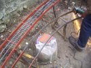
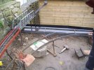
Most framing now painted and the steels for the 180 degree curve on a gradient down to the dockside is bent up and mostly in place, we got further than this photograph shows, but the light went.

Now contemplating how best to set up the dockside track base, shown mocked up below with a piece of timber, which it won't be.

100_1767.jpg
 

David B

Western Thunderer
I’m loving the way the new line is shaping up Simon - there’s something about the design, the use of the space, the welded steel supports, the scale, the water and the setting which are all coming together to make this rather special. Is it possible for a model railway to have charisma? (Discuss) - if so, this line already has it IMHO.
 

Simon

Flying Squad
Thank you David, it is certainly unlike anything I have done before(!)

In today's light, yesterday's progress.

100_1772.jpg

100_1774.jpg

100_1777.jpg

A few issues with gradients, the curve down to the "quay" possibly doesn't drop away enough, although this will make shunting and running over it easier.

I could introduce a gradient on the line along the quay or (more likely) reduce clearance under the girder bridge to what is strictly necessary. Bogie bolsters aren't that tall!

It is so cold that the red oxide hasn't gone off properly yet, but a bit of heat and time will sort that out.

Concreting getting nearer....

Simon
 

Neil

Western Thunderer
Once the track is down what will you be doing with the ground level Simon. I guess that the railway isn't going to be on stalks.
 

Simon

Flying Squad
I'm not entirely sure, I really want/wanted water to flow alongside the railway from the top of the "scene" into the trough, but this is looking a bit challenging, not least as the track goes into the ground at the top end, so getting water under the track is problematic. An aqueduct?

There are various features I want to build in, station platform, signal box, level crossing, goods yard, but I don't want to create any kind of "model village" effect. As it gets built, like all model railway plans there is less space left than I thought there would be.

There will be lots of plants and planting though.

So sort of making it up as I go along, the overriding factor in everything being aesthetics.

Not a concept that comes readily to mind looking at the current state of play!

Simon
 

Neil

Western Thunderer
Avoiding the model village sounds good as does lots of plants and planting. I'm sure I've mentioned it before but this railway in the garden from the August 71 Railway Modeller has stuck in my mind over all the intervening years.

rm august 71.jpg

Something magical about the light.
 

Simon

Flying Squad
Another splendid day, mostly spent talking, but with a garden interlude too...

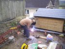
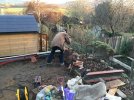
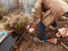
Esteemed visitor assisting Dave with the fabrication of the dockside track base.

100_1796.jpg

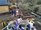
Its none other than Steve Cook, looking away while welding takes place.

100_1797.jpg

The newly fabricated dockside base placed in position.

100_1802.jpg

And being welded to upright angle driven into the ground.

100_1806.jpg

There is a bit of jiggery pokery required where the curved track base transitions into the dockside base, but we think it is do-able with lump hammer and grinders(!)

Thank you to both Steve and Dave for a really enjoyable day.

Back to Plastikard and the signal box tomorrow maybe.

On another subject, albeit related, Giles very kindly sent me one of his genius point motor assemblies which Steve and I tested out with a 1.5 volt battery this evening. It is a beautifully clever design that works very well and we both thought it perfect for changing the points on this line. I can, I think, mount the assembly directly to the side of my track base and drive the points directly from the horizontal drive arm. Giles' fiendishly clever design incorporates the microswitch for switching the crossing polarity, all of which will be hidden "underground" beside the track base under a suitable building. A signal box even, maybe with functioning point rodding linking everything, or maybe that is too ambitious?

I'll have fun finding out either way - thank you Giles for a brilliant design!

Simon
 

Simon

Flying Squad
Another terrific day in the garden, no rain and not too cold and in the company of a good friend with a welder and good ideas!

Today's task was to "adjust" the gradient of the curved track base and then get it attached to the dockside track base framing. We started by grinding cuts into the steel sides to the track base in two places, such that we could put vertical bends in the steel to get the track base level with the dockside where it would be joining it.

Putting in a cut, first pair above tile on bag of sand.

100_1863.jpg

Having adjusted the slope with the lump hammer, the connecting pieces of steel are next welded into place.

100_1869.jpg

100_1870.jpg

With the curved track base now fixed to the dockside, Dave completes the job by welding spacers between the steel flats.

100_1873.jpg

The goods siding base was then fabricated and is seen here being welded to supporting angles driven into the ground.

100_1881.jpg

The failing light is hopeless for progress, but creates interesting visual effects, here Dave finishes by welding the dockside framework to vertical steel angles driven into the ground behind the bridge.

100_1890.jpg

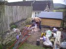
I flatter myself with the notion that this shot gives an idea of the interesting viewing angles the whole ghastly mess will offer once it is finished(!)

A great day's progress, several issues resolved and feelings of moderate enthusiasm towards further work, scheduled for next Monday:)

Thank you very much to Dave, as ever.

Simon
 

Dikitriki

Flying Squad
Simon,

What's the radius of the dockside curve, and what do you intend to run round it?

When I first saw that you were going to work on another railway, I did wonder whether you would have the same approach to the girder and concrete base construction.......silly me!

Richard
 

Allen M

Western Thunderer
Hi Simon
When I see this it reminds me of some photos I saw many years ago of the Liverpool Overhead Railway.
Thanks for your reports,
Regards
Allen
 

Simon

Flying Squad
Simon,

What's the radius of the dockside curve, and what do you intend to run round it?

When I fist saw that you were going to work on another railway, I did wonder whether you would have the same approach to the girder and concrete base construction.......silly me!

Richard
Richard

It won't be you who's being silly....

In fairness to the lunacy here in Batheaston, it would I think be very difficult to have created these different levels and shapes in timber, and I do know that this method works(!)

It is also informed by my knowing Dave. We were chatting over dinner last night and being the age that we are got around to discussing each others mortality. I said to him that I'd be lost without him on the welding front (obviously not only/mainly on the welding front - I'm not completely whatever that would make me!) and he observed that if such a situation ever arose then I would need to get on and learn how to weld!

He is phenomenally talented (in many ways) and such a good friend, all of which makes my lunacy less lunatic, possibly...

The radius of the curve down to the quay is circa 6 feet and I am moderately confident that most things will run around it, what needs to go around it are wagons, bogie bolsters, the Ruston, Pannier and 03.

I tested stuff and even the recently built Borail runs around it, but it does look very odd on such a sharp curve.

I doubt coaches will or would, so those enthusiast tours will have to be by brake van!!

What I do think is going to be challenging is transitioning from level to uphill and downhill at each end of the curve, particularly the bottom with a sharp point and fairly immediate climb. I expect all sorts of issues and wrinkles will be required to keep stuff reliably staying on the track....

Onwards and upwards!

Simon
 

AJC

Western Thunderer
I tested stuff and even the recently built Borail runs around it, but it does look very odd on such a sharp curve.

Plenty of precedent for that sort of thing at Redbridge and Southampton Docks. A chap I know used to be a shunter at the former and one of the incidents he described involved precisely the buffer-locking jackknifing we’re all so familiar with in our model worlds…

I look forward to hearing how the pannier copes!

Adam
 

Simon

Flying Squad
Yes you are right Adam, I think that my "normal long" bolsters may need extended couplings to get down there. On the other hand, six feet radius in 1/32 is roughly the same as a bit more than 2 feet in 4mm scale, so not "that" sharp in toy train terms!

I went back to work today, but nipped back at lunchtime to take some shots of what Dave and I got done yesterday.

Here is an overall high level view showing all the main track base frames in place.
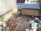
100_1893.jpg

I think I intend to continue the base to the right in the above view, straight on as a headhunt to the quay, but with another sharp right hand point that will send out a curved line which comes towards the house but on the other side of the central area. This will be a sharper curve still, I imagine it to be the domain of the Ruston, Manning Wardle and peculiar railcars, and will/may lead to some sort of "light railway" thing up the "right hand flowerbed". Possibly. It could be operated from the path below, this would certainly offer some very good eye level views without getting down on to the ground. Food for thought.

Back to damage already inflicted, here we see the higher level goods siding and access curve, from the viewpoint of the "other bank" of the quay.
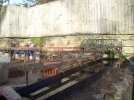
100_1894.jpg


I'm quite pleased with how this is shaping up, what isn't a problem is accessing the end of the quay line towards the bridge for uncoupling, as I had sketched it out this was an issue, but there is happily more "length" in the area than I had imagined it. That said, the upper goods siding is really quite short!
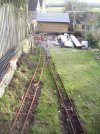
100_1904.jpg

Back towards the house, a long shot of the whole set up. I am also beginning to think that lowering the "lawn" in the foreground by about a foot would improve the feel of the whole thing, the area behind the lawn will be a couple of steps lower still, so the railway "surrounds" us as operators and viewers. I think there might be enough places around the garden where excess soil could be re-deployed. Lowering the "lawn" will yield a lot of quite nice and useable Bath stone pieces, possibly/hopefully. A hell of a lot of digging though(!)

And finally the view that possibly "justifies" everything, along the water with lots of reflections. You have to imagine that on the left there is a stone wall up from the water to the top of the steel of the track base, while on the right plants grow along the edge of the water, obscuring the edge of the abyss of doom and hiding the track heading for the shed. The right hand framework under the girder bridge will be made of stone.
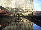
100_1897.jpg

Phew!

All in all I am feeling quite fired up by the whole thing, lots to do but lots of interesting and "different" possibilities.

Simon
 

Pencarrow

Western Thunderer
Hi Simon, just wondering... Have you had any of those conversations with neighbours, you know, the ones where they look at you as though you've gone mad... The one where you explain to a non-enthusiast why you've replaced a lawn with a tangle of welded steel?
 

Tim Watson

Western Thunderer
Hi Simon, just wondering... Have you had any of those conversations with neighbours, you know, the ones where they look at you as though you've gone mad... The one where you explain to a non-enthusiast why you've replaced a lawn with a tangle of welded steel?
Just tell them it’s an art installation - it will be. I can see the need for a backscene on the garden fence...

Tim
 

Simon

Flying Squad
Another day out in the garden, beautiful sunshine, perfect for a bit of "gardening"....


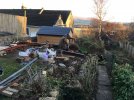
Dave contemplates the work site in the sunshine, note the luxuriant vegetation right foreground....
IMG_0093.jpg

Vegetation largely gone, quay base extension built, support legs being knocked into place.

IMG_0098.jpg

And being welded to the frame. Two cunning plans going on here, first off is the re-purposing of the large lift out bridge from the last line (in this picture) as the final piece of the headhunt to the quay line, it will thrust out cheekily into free space and end several feet over the path below. We will be welding a piece of steel over the end to avoid "rolling stock free fall" situations.

IMG_0100.jpg


The second cunning plan is to build a further track base up the newly cleared bed to lead to a potential light railway vestigial terminal with one siding and a suitably half baked building. I have several items of rolling stock that will suit such a line, and the "clever" part is that it will be operatable from the pathway below without back ache. Further thinking and doodling required.

IMG_0099.jpg


The headhunt bridge is a substantial bit of metal, so the end of the quay base to which it will be attached needs to be secure, hence welding a horizontal steel angle to the two uprights at the end, gardeners look away now(!)

IMG_0106.jpg

The rose arch in the background is shot, so poor Dave has the contract to make a replacement, in the meantime I need to rebuild the wall ground below up a bit to support the headshunt bridge.

Lots left to do....
 
Top