George is Here

GeorgeO1

New Member
Hi Members,,
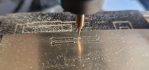
I have been a member of the 3mm society in the UK since 1973 - am always looking for advice and tricks for super fine scale - am currently using a Genmitsu 3020 cnc machine with a 0.3mm milling cutter working on 0.4mm titanium to try and make finer scale valve gear - am still trying to fine tune my recipe - any advice?

Best, G
 

simond

Western Thunderer
Welcome!

No advice, but lots of interest. Please do show us what you’ve done, what went right, (and what didn’t)

and photos!

cheers
Simon
 

Brian McKenzie

Western Thunderer
. . . always looking for advice and tricks for super fine scale - am currently using a Genmitsu 3020 cnc machine with a 0.3mm milling cutter working on 0.4mm titanium to try and make finer scale valve gear - am still trying to fine tune my recipe - any advice?

A tough recipe. Try baking first with a softer material and larger diameter cutters, whilst gaining experience. Then progress to smaller tools and tougher materials, but suggest 303 stainless rather than titanium - that is if you don't want to use steel.

I suspect breakage of tools when cutting internal corners will be an almost insurmountable problem for you.

In cheeky monkey mode - trade your machine for an EDM wire-cutting type, perfect for such work :eek: .

Alas 0.3mm dia cutters aren't compatible with any machine that has even the tiniest smidgeon of backlash (user quote, "and there is only very little backlash between the screw and the nut"). Another biggie is minimising eliminating cutter runout - beyond what ER collets e.g. might offer.

To reduce breakage of such delicate cutters, table movements need to be very tightly controlled, way beyond the ability of hobby machines and even those in basic industrial use. A helpful programming feature is to be able to slow the feed rate momentarily when changing direction in internal corners. This prevents loading the tool excessively when it engages two sides simultaneously.

Looking forward to photos of your progress.
 

GeorgeO1

New Member
A tough recipe. Try baking first with a softer material and larger diameter cutters, whilst gaining experience. Then progress to smaller tools and tougher materials, but suggest 303 stainless rather than titanium - that is if you don't want to use steel.

I suspect breakage of tools when cutting internal corners will be an almost insurmountable problem for you.

In cheeky monkey mode - trade your machine for an EDM wire-cutting type, perfect for such work :eek: .

Alas 0.3mm dia cutters aren't compatible with any machine that has even the tiniest smidgeon of backlash (user quote, "and there is only very little backlash between the screw and the nut"). Another biggie is minimising eliminating cutter runout - beyond what ER collets e.g. might offer.

To reduce breakage of such delicate cutters, table movements need to be very tightly controlled, way beyond the ability of hobby machines and even those in basic industrial use. A helpful programming feature is to be able to slow the feed rate momentarily when changing direction in internal corners. This prevents loading the tool excessively when it engages two sides simultaneously.

Looking forward to photos of your progress.
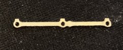
Here is my best piece so far with titanium 2023-11-15 09.12.56.jpgand 0.3mm cutter - it is 21 mm in length and is a coupling rod from a J70 Tram Engine I am building in 3mm scale - it needs some fine dressing with a stone - the holes are 1mm in diam and the use of the 0.3mm mill is to work around the fine inside radii.
 

-missy-

Active Member
Hi George.

I hope you don't mind me pointing these out but I have some experience in this area machining 2mm scale stuff.

1. As Simon says, why Titanium? It seems a little odd to use such a unforgiving material to use which you are not really using the materials advantageous properties. I have always stuck to Brass, Nickel Silver, or even Steel in extreme cases for coupling rods.
2. 0.3mm cutters are absolutely unforgiving, especially carbide. All you have to do is look at them wrong and they will break. Have I used them? Yes but only if I absolutely have no other option. I always aim for the largest diameter cutter I can get away with. Anything less than 0.5mm I treat with the utmost care, running them way under their stated capabilities.

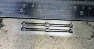
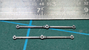
I have recently completed a set of coupling rods for an engine using a 0.4mm cutter on 0.5mm thick Nickel Silver with a feed rate just under 5mm/min without any issues (other than them taking a bit of time because of the pocketing routine I used).

1700074763045.png

1700074831950.png

1700074876410.png

I hope that helps a little bit. Apologies if its a bit preachy.

Julia.
 

GeorgeO1

New Member
Hi George.

I hope you don't mind me pointing these out but I have some experience in this area machining 2mm scale stuff.

1. As Simon says, why Titanium? It seems a little odd to use such a unforgiving material to use which you are not really using the materials advantageous properties. I have always stuck to Brass, Nickel Silver, or even Steel in extreme cases for coupling rods.
2. 0.3mm cutters are absolutely unforgiving, especially carbide. All you have to do is look at them wrong and they will break. Have I used them? Yes but only if I absolutely have no other option. I always aim for the largest diameter cutter I can get away with. Anything less than 0.5mm I treat with the utmost care, running them way under their stated capabilities.

I have recently completed a set of coupling rods for an engine using a 0.4mm cutter on 0.5mm thick Nickel Silver with a feed rate just under 5mm/min without any issues (other than them taking a bit of time because of the pocketing routine I used).

View attachment 201416

View attachment 201417

View attachment 201418

I hope that helps a little bit. Apologies if its a bit preachy.

Julia.
Hhi To Simond and you, Julia

The reason for titanium was simple
I love a challenge and the idea of attempting to use the material was an itch I had to scratch. and I had some. I have also made the same rods in nickel silver and stainless steel.


Those rods of yours look very good indeed and I would like to know more about your feeds and speeds - My feeds and speeds for the above were: 8000 rpm; vertical feed rate 0.25mm; horizontal feedrate 2.5mm; step over for helix cut in holes 40%

Best,

George
 

JimG

Western Thunderer
I also wonder why you are using titanium. :) I did a quick search for its machining properties and found that it is not an easy metal to machine. I work with a hobby CNC mill (Seig KX1) and its limitation for very small diameter cutters is its top spindle speed of 7000rpm and I spent a fairly expensive time when I started using it, trying to find out what I could get away with. I cut a lot of styrene where carbide cutters are required, so I use carbide cutters for everything. I built up a fair pile of broken cutters finding out the hard way. :)

But a few years ago I found a feed and speed calculator which allowed me to feed in my low spindle speeds and gave feed, speed and depth of cut parameters which worked for me with various materials.

Feed and speed calculator

It's a bit pricey, but I think you can still get a 30 day trial period. I used this period to calculate the parameters for small cutters I would want to use on brass or mild steel and they have worked for me and my cutter breakage is now very low. I've just checked the tool database on my CAM program and I have a 0.5mm carbide two blade slotting cutter working at 6000rpm with a feed of 25mm/min at a DOC of 0.1mm on brass. For mild steel I would half the feed rate to 12mm/min. I also try to avoid climb milling.

Jim.
 

adrian

Flying Squad
Steel in extreme cases for coupling rods.
extreme cases!! When modellers agonise with painful depth and detail on loco livery colours, down to the colour of the primer/undercoat then blithely accept completely the wrong colour on the motion just seems bizarre to me. Motion and valve gear was made in steel so that is the only option for getting the colour correct on our models. [ apologies - yet another soapbox of mine! ]
 

-missy-

Active Member
extreme cases!! When modellers agonise with painful depth and detail on loco livery colours, down to the colour of the primer/undercoat then blithely accept completely the wrong colour on the motion just seems bizarre to me. Motion and valve gear was made in steel so that is the only option for getting the colour correct on our models. [ apologies - yet another soapbox of mine! ]

You are totally right Adrian.

I don't think its that obvious in 2mm scale though, I would say that 99% of coupling rods in this scale are Nickel Silver. In larger scales, yes.
Certainly if I was producing stuff to level and quality of guys on this forum, then I would definitely be using the correct materials where I can.

Julia :)
 

Lyndhurstman

Western Thunderer
extreme cases!! When modellers agonise with painful depth and detail on loco livery colours, down to the colour of the primer/undercoat then blithely accept completely the wrong colour on the motion just seems bizarre to me. Motion and valve gear was made in steel so that is the only option for getting the colour correct on our models. [ apologies - yet another soapbox of mine! ]
Unless you're a Rust God #youlookingatmekid? :)

Cheers

Jan
 

-missy-

Active Member
Those rods of yours look very good indeed and I would like to know more about your feeds and speeds - My feeds and speeds for the above were: 8000 rpm; vertical feed rate 0.25mm; horizontal feedrate 2.5mm; step over for helix cut in holes 40%

Hi George.

I know the feed rate was running at around 5mm/min. As for the spindle speed, I am afraid I cannot answer that as I have never checked it (must get round to doing that sometime). I have chopped my machine around quite a bit and never got round to checking the final speed. I do know that I am running these cutters way under the recommended speeds though.

Sorry.

Julia.
 

GeorgeO1

New Member
I also wonder why you are using titanium. :) I did a quick search for its machining properties and found that it is not an easy metal to machine. I work with a hobby CNC mill (Seig KX1) and its limitation for very small diameter cutters is its top spindle speed of 7000rpm and I spent a fairly expensive time when I started using it, trying to find out what I could get away with. I cut a lot of styrene where carbide cutters are required, so I use carbide cutters for everything. I built up a fair pile of broken cutters finding out the hard way. :)

But a few years ago I found a feed and speed calculator which allowed me to feed in my low spindle speeds and gave feed, speed and depth of cut parameters which worked for me with various materials.

Feed and speed calculator

It's a bit pricey, but I think you can still get a 30 day trial period. I used this period to calculate the parameters for small cutters I would want to use on brass or mild steel and they have worked for me and my cutter breakage is now very low. I've just checked the tool database on my CAM program and I have a 0.5mm carbide two blade slotting cutter working at 6000rpm with a feed of 25mm/min at a DOC of 0.1mm on brass. For mild steel I would half the feed rate to 12mm/min. I also try to avoid climb milling.

Jim.
Thanks Jim, I assume you are referring to the CNCookbook - it was that superb desktop tool that got me to the correct chipload for my endeavours and you are all correct the margin of error between grinding and cutting and between cutting and snapping are razor blade thin - I also use a piece of plastic dpc material on top of the wasteboard - I have some specially made clamps which form a well to surround the piece to be cut and I put a drop of Molyslip MWF as a lubricant - its quite thick so doesn't fly all round the room.

Best
G
 
Top