4mm Holt (ex-Delph) - A P4 layout under construction

Dave Holt

Western Thunderer
With my loco construction (currently rebuilt Royal Scot 46109) having run out of steam for the moment, I thought I might post something about my P4 layout. Actually, I'm not sure this should be here as the section is called "Layout Progress) and the layout hasn't made any progress for some years - awaiting conversion of the garage into a model railway room. Despite this reservation, I'll plough on.

The layout has its origins in a house move. My first intention had been a continuous oval depicting Knighton, on the Central Wales line and a full sized track plan was created by cutting paper templates for the point work. However, a house move resulted in much less space. Some time later, I bought a book about the Delph Donkey (by Michael & Peter Fox), my interest being prompted by my mother having travelled on it for a brief period during the Second World War when she was an agency short hand typist at a dye works in Delph. A photo of an Ivatt Class 2 2-6-2 tank departing the station, propelling two aged push-pull coaches, particularly piqued my interest.

The book also contained a track plan (dating back to the 1880's. I found that a shortened version of the station and yard area could be accommodated on a layout across the diagonal of the spare bedroom, using a kick-back arrangement for the fiddle yard. A small scale track plan and general layout arrangement was developed, including cross sections at various places along the layout - the station/yard area are cut into a hillside with a road and river at lower levels to the front. Quite nice natural framing. However, before construction could commence, a further house move resulted in the need for a further evaluation.

In the new house, the second bedroom was smaller and the proposed layout wouldn't fit. However, a de-mountable layout, in sections, could be occasionally erected in the through lounge/diner and sun lounge extension. Indeed, such an arrangement would allow a dead scale model of the station/yard area, without the need for any compression. Over the years, various books, articles and track plans, including a large rating plan, had been acquired and contact made with someone who had been involved in another model of Delph and had useful information. A friend from the Scalefour Society kindly offered to create the scale track plan in Templot by overlaying a scan of the rating plan. This file was subsequently imported into a CAD file, allowing some scenic features and baseboard arrangement to be added. The resultant layout plan is shown below.
Track layout0070.JPG
The idea was to have the main boards extend to just behind the mill siding with light weight hang-on scenic boards to carry the scenery behind the track.

Although the track layout, up to the yard throat, is a scale model of Delph. the scenic feature at the left, to disguise the exit to the cassette fiddle yard and the configuration of the the mill behind the siding are not prototypical so the layout name was changed to "Holt". The long bridge (short tunnel?) and the cottages in the roughly triangular area at the left are on the Delph branch, but further along towards the junction with the main line, being located at Dobcross (Dob Cross?). The mill was intended to be a late period (1904), red brick, replacement for the actual, rather gloomy stone built mill which was behind the station (now demolished, I believe). In recent times, I've veered back towards the prototypical mill, so the name change might not be required, now, but the station and signal box already carry the Holt name, so I'll stick with it. Anyway, by not being Delph I can vary the train services and stock beyond the limited variety that actually ran there.

So far, the main boards are complete (but not the fiddle yard or scenic boards), track laid, ballasted and wired up. The Station platform and building, the goods shed and the signal box were all made for me by Peter Leyland. Here are a couple of shots of the layout, not necessarily in its current state, to give some idea of the overall arrangement.
Delph_gen_019.JPG
Delph_gen_022.JPG
That's friend, David Clarke, scraping paint off the rail heads prior to a running session.

Dave.
 

Dave Holt

Western Thunderer
The intention was always to build the layout to be taken to exhibitions so the scenic part was broken into four reasonably manageable sections, The location of the joints was determined by the track layout and some scenic features. It was not possible to arrange for nice symmetrical boards which could be bolted back-to-back for transport, as many exhibition layouts are, and the four sections vary greatly in length and width. Transport was intended to utilise a multi-level, wheeled trolley, which would accommodate the maximum length and width of the various sections. With the passage of time and lack of completion, etc., it seems very unlikely that the layout will ever attend any exhibitions, but at least the sections can be stored and moved about at home reasonably easily.

No legs are provided as the idea was to have a separate support structure which would be erected and levelled up before sitting the layout boards on top. This structure has not been made (yet?) and recent ideas replace the original wooden construction with one made from rectangular and square hollow section steel.

The boards are made from a marine grade of MDF (nothing like the stuff you find in B&Q) with a 12 mm top, in the area where the track is, and 6 mm ribs forming the support framework and front scenic extension. Large lightening holes in the ribs both reduce weight and allow wiring to pass through. The end plates are laminated from two 6 mm layers with a thickness of card between. The need for the card was to allow the female halves of the locating pattern makers dowels to sit slightly below the outer surface. Although the end boards are flat, they are not necessarily square to the back edge of the boards and the joint in the top surface is kinked or stepped, to suit the track layout, at two joints.

All the board construction (and track laying) was done at a friend's workshop in Leamington Spa with much help from the friend. He isn't a modeller, but has a lot of experience with using this type of material. Here are some views of the boards under construction. Sorry for the poor quality, but these have been enlarged from some rather small original files.

The tops laid out (outside) to show the overall spine of the layout.
Delph boards 02.JPG

Boards under construction showing the lighted support ribs. In these shots, two boards are connected together.
Delph boards 05.JPG
Delph boards 06.JPG

Delph boards 08.JPG
In the last shot, the staggered joint in the top can just about be seen. This was done to keep the joints more or less square to the track and to avoid some point-work. The recess at the front is where the coal drops are.

Once the main spine was completed, the scenic sections in front were grafted on.
Road way dropping down from the station towards the coal drops.
Delph boards 15.JPG

The transported Dobcross scenic break.
Delph boards 17.JPG
Dave.
 

LarryG

Western Thunderer
Good to see the layout is back on your agenda Dave. I used to wonder where a Bulleid Pacific and Royal Scot fitted into the scheme, but I know you just like building engines that turn you on.

I always hoped the fireman would go sick on the Delph Pilot turn when I worked at Lees! It also included other duties and was a Fairburn 2-6-4T turn in 1960. The other Fairburn wasn't needed until the evening for Clegg Street parcels. An Austerity would have been interesting on the Delph branch curves!
 

Dave Holt

Western Thunderer
As you say, Larry, some of my locos are not related to the layout but are just types I like. At some huge stretch, the Scot could appear on a Wakes Special, especially since it's Holt, not Delph.
In all the information I've accumulated, there is very little about freight train operation and I have not been able to find any photographs of the Delph goods actually on the branch or at Delph itself. Not even Jim D seems to have taken any.
According to the Lees loco diagram sheets, the Delph pick-up goods fell into the Motor link in the 1950s. I'm not sure if this implies that it was worked by one of the motor fitted 2-6-2 tanks or if it was just the crew was from the link and any suitable loco would be used? One would imagine that a Lanky A class would be more appropriate.
In my version, a WD is more than a possibility. In fact, with small wheels, close together, the fixed wheelbase id not much different from the standard MR wheelbase used on the Fowler 2-6-2 tanks, so the curves on the branch would not have been too big a problem. WDs were certainly used on other single line branches in the area.
Dave.
PS. 16'-6" fixed wheelbase for the 2-6-2 tank and 16'-3" for the WD.
 
Last edited:

Dave Holt

Western Thunderer
Having explained some background to the layout and covered the assembly of the base boards, the next topic is track.
The track plan was done using Templot and all the point work made using rivetted ply sleepers. This was all done for me by Tony Wilkins, a recognised expert in P4 point construction. The plain track, except for a few short lengths of rivetted construction, was plastic based, flexible track from C&L. All the moulded sleeper ties were removed and the sleeper spacing adjusted to suit track panel ends and LNWR spacing for short panels in the yard area. In this, I assumed the running line would have been relayed in 60 foot panels, whereas the loop and yard would remain in 30 foot lengths.
The point work was delivered by Tony, temporarily attached to hardboard sheets, as a mixture of individual points and larger assemblies, as shown below.
Throat track-work.JPG

Here's the same unit of point work (plus a bit extra) laid but not fixed in position on the baseboard.
track_trial_01.JPG

The area where track would be laid was covered in 3 mm thick cork, reinforced at the board joints by 3 mm thick wood strips, as seen here at a later stage of construction.
Sleepers_002.JPG
Sleepers_001.JPG
These shots also clearly illustrate the staggered board joints mentioned in a previous post. Also seen are the rivetted ply sleepers used to provide a more substantial rail fixing than the plastic sleepers at the board joints.
My original plan was to glue down the Templot plan to the cork and lay the track on top of the plan. I've seen this done on other layouts shown on the net, but I found the paper templates wrinkled and could not be kept flat so, instead, I marked the track positions onto the cork using pins and ink dots. These marks were then joined up with marker pen to shoe the rail positions, as also seen in the photos above.
The point work was then positioned over the marks and carefully adjusted for alignment, etc., and its location defined by inserting pins into the cork at sleeper and point assembly ends.
track_03.JPG
The unit of point work could then be carefully lifted out, PVA glue applied, the point replaced and weights placed whilst the glue set. I found that there was a very slight mismatch in height between the rivetted points and the plastic based plain track, so paper strips were fixed under the lower part adjacent to the joint, before fixing the track.
track_01.JPG
Once the points were fixed down, the linking sections of plain track were prepared and a smooth alignment checked by sighting along before pin marking and track laying using the same method as the points.
Dave.
 

Dave Holt

Western Thunderer
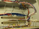
Once all the track was fixed down, I thought it best to wire everything up and get the electrics fully working before any ballasting or scenic work. I wanted to be able to operate with either DC or DCC so provision was made for both. Actually, this is very simple since both systems are just two wires to the track, just requiring two different sets of socket connectors for the different control systems. An experience modelling friend advised that, for DC operation and to avoid loads of isolation switched, power to sidings should be powered from the point switches and that wiring could be reduced by using a common return arrangement. To be honest, I struggled (and still do) to get my head around the idea that you could link DC and DCC track feed and 12V D/C and 16V A/C supply returns all together but it works!
A further complication was that I wanted the control panel, which mainly replicates the function of the signal box, to be located right at the buffer stop end of the station whilst the main track feeds were right at the other end, on the single track approach. This resulted in quite a lot of wires running the full length of the layout.
To try to ensure reliability and avoid excessive voltage drops along the steel rails, I fitted two dropper wires to every separate piece of rail, however short. The droppers were soldered to the foot of the rail on the back (non viewable) side using bare tinned copper wire. I found the old, greasy Fry's Fluxite flux quite effective for the copper to steel joints. The droppers pass through the board top and are soldered to bare tinned copper wire bus bars, supported on brass screws, which follow the track plan under the boards.
Also under the boards and the Tortoise point motors, signal servos and their control boards and a couple of local 12V D/C power supplies for these.
Alex Jackson uncoupling magnets are also fitted underneath and these have their own power supply, separate from the common return systems. The magnets seem to work better at a slightly higher voltage and the supply is from a separate, variable output power supply unit, current set at about 18 - 20 volts.
Multi-pin D connectors connect between boards and to the control panel, two being required for the latter.
There's no wiring diagram, but there are connection/tag lists for each board and I kept the same tag numbers throughout, even where no connection is required on a particular board. I also tried to keep to a consistent wire colour for different functions.
I also tried to keep the wiring fairly neat with the main runs along the rear edge of the boards. Some layouts have wiring like spaghetti, which must make tracing quite difficult.
Here are a few photos of the resultant wiring.
elecs_001.JPG
elecs_003.JPG
elecs_007.JPG
elecs_008.JPG
elecs_011.JPG

Dave.
 

Herb Garden

Western Thunderer
Once all the track was fixed down, I thought it best to wire everything up and get the electrics fully working before any ballasting or scenic work. I wanted to be able to operate with either DC or DCC so provision was made for both. Actually, this is very simple since both systems are just two wires to the track, just requiring two different sets of socket connectors for the different control systems. An experience modelling friend advised that, for DC operation and to avoid loads of isolation switched, power to sidings should be powered from the point switches and that wiring could be reduced by using a common return arrangement. To be honest, I struggled (and still do) to get my head around the idea that you could link DC and DCC track feed and 12V D/C and 16V A/C supply returns all together but it works!
A further complication was that I wanted the control panel, which mainly replicates the function of the signal box, to be located right at the buffer stop end of the station whilst the main track feeds were right at the other end, on the single track approach. This resulted in quite a lot of wires running the full length of the layout.
To try to ensure reliability and avoid excessive voltage drops along the steel rails, I fitted two dropper wires to every separate piece of rail, however short. The droppers were soldered to the foot of the rail on the back (non viewable) side using bare tinned copper wire. I found the old, greasy Fry's Fluxite flux quite effective for the copper to steel joints. The droppers pass through the board top and are soldered to bare tinned copper wire bus bars, supported on brass screws, which follow the track plan under the boards.
Also under the boards and the Tortoise point motors, signal servos and their control boards and a couple of local 12V D/C power supplies for these.
Alex Jackson uncoupling magnets are also fitted underneath and these have their own power supply, separate from the common return systems. The magnets seem to work better at a slightly higher voltage and the supply is from a separate, variable output power supply unit, current set at about 18 - 20 volts.
Multi-pin D connectors connect between boards and to the control panel, two being required for the latter.
There's no wiring diagram, but there are connection/tag lists for each board and I kept the same tag numbers throughout, even where no connection is required on a particular board. I also tried to keep to a consistent wire colour for different functions.
I also tried to keep the wiring fairly neat with the main runs along the rear edge of the boards. Some layouts have wiring like spaghetti, which must make tracing quite difficult.
Here are a few photos of the resultant wiring.
View attachment 181292
View attachment 181293
View attachment 181294
View attachment 181295
View attachment 181296

Dave.
Dave,

That wiring looks great! One of my electrical engineering colleagues told me when I started in design that good wiring in its layout should give someone looking at an overview of how it all works. Rather that just looking like a bundle of wires. I think you've captured that sentiment here.

I second Michaels comments about the baseboards

Herbie
 

David Waite

Western Thunderer
Hi Dave
Thats a lovely neat job you have done.
Putting dropper wires to each piece of rail is certainly the way to go I have done the same, so many people just rely on fishplates for the circuit and they are bound to fail at some point, my friend has a G gauge garden railway with over 400 feet of rail he has put a Bonding loop on the rail sections at each fishplate the railway has been running faultlessly in all weather for 14 years or more.
I do second what Herbie said, and some form of order to cabling certainly makes fault finding easier, I have been using slide on cable number tags to some of my wiring to make build easier, “Less confusion“.
David.
 

Dave Holt

Western Thunderer
Thanks for the comments.
The layout was intended to exhibit-able, but I doubt it will ever reach that stage now, and operated from the front. The main control panel, which more-or-less replicated the signal box is located at the extreme end of the layout near the station buffer stops. It control the points and signals which would be under the control of the signalman, leaving the hand operated yard points, and the AJ uncouplers, to local switches mounted in the facia board, local to each item.
Also controlled from the panel are the section/control type switches and the bell code equipment.
The upper face of the panel is a track mimic diagram, laid out as it would be above the frame in the box.
Here's the outside of the finished panel'
Control_012.JPG
As can be seen, the levers are colour coded by function. Points and signals are electrically interlocked although there is no physical restraint on pulling a wrong lever or in the wrong order - it's just that nothing happens.
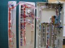
I was wary of the reliability of the Tortoise change-over contacts, so crossing polarity, point motor feed and the LED point route indicators are all fed from the multi-pole switches. The diamond crossing polarity switching necessitated more poles than a toggle switch could provide, so that switching also involves a couple of relays inside the panel. As with the layout wiring, I've tried to keep the inside of the panel as neat as possible.
The ends of the panel mount the two multi-pin connectors to the layout at one end and the power in and sockets for DC and DCC controllers at the other.
Control_004.JPGControl_008.JPG
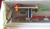
Also mounted in the panel is one of the control boards for the bell code mechanism. This and the local 12V D/C power units for the signal servos were made for me by Richard Challis. One of several people who have helped me get even this far.
Control_010.JPG
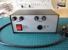
Finally, for this post, a view of the power supply module. I don't appear to have any photos of the inside of this and can't really remember exactly what is inside or why there are two sets of different rated fuses. It must all have made sense at the time.
Control_009.JPG
Dave.
 
Last edited:

Dave Holt

Western Thunderer
Hi Herbie.

The case for the panel (and, as far as I can remember, all the electrical components) came from Squires. They call it a console case.
Obviously, the upper and lower aluminium panels come blank and the holes and diagram were done as part of the project. The lettering is Letraset and was done by a friend who is a signwriter. The track diagram was done using coloured permanent marker pens and the whole lot was then sealed under lacquer.

Dave.
 

Pencarrow

Western Thunderer
Hi Herbie.

The case for the panel (and, as far as I can remember, all the electrical components) came from Squires. They call it a console case.
Obviously, the upper and lower aluminium panels come blank and the holes and diagram were done as part of the project. The lettering is Letraset and was done by a friend who is a signwriter. The track diagram was done using coloured permanent marker pens and the whole lot was then sealed under lacquer.

Dave.

Took me a while to find it but here's the product info for the console case from the Squires catalogue:rps20230227_082849.jpg

Could be just what I'm after.
 

34091 Weymouth

Western Thunderer
Took me a while to find it but here's the product info for the console case from the Squires catalogue:View attachment 181458

Could be just what I'm after.

A very enjoyable read so far Dave, I've always liked seeing your p4 models & this layout is going to be lovely when finished.

BTW these boxes are a treat. Never knew squires did them. I think I might order a small for my own layout.

Look forward to seeing more.

Si
 

Dave Holt

Western Thunderer
Thanks again for the comments. I'm definitely not a professional electrical person, i just like it to look neat and tidy. I did make my own wiring harness for the Trifield motorbike I built - all properly laced. I was quite proud about that.
Having said I have no idea what's inside the power supply, I just had to refresh my memory, so here it is.
IMG_2507.JPG
Just the mains switch, some fuses and two transformers, wired in parallel. 240V in, 16V A/C out. The parallel circuits explain why there are two sets of fuses, mains supply and output for each transformer.
There's a sort of "H" shaped, horizontal plasticard divider, visible between the transformers and near the front up-stand. I can only think I put this in so that should any of the upper (output) wires break of become detached, they can't fall onto the mains connectors at the bottom.
Dave.
 

David Waite

Western Thunderer
Hi Dave
one word Superb
In the past I have worked on hundreds of industrial control panels you have put many electricians to shame
you would have made a great installation sparkie.
David.
 

LarryG

Western Thunderer
For some reason, I "lost" this thread, so am only just catching up.

Re the Delph branch goods, it may have been in the 'motor link' if it was part of a passenger shift. I was told it had 15 minutes at Delph to knock wagons about before shunting the other sidings along the branch (the loco always being at the mainline end to prevent runaways). Everything was timed to fit in between Standedge traffic. I'm pretty sure it then did Mossley yard before returning to do the Royal George sidings and soap factory. Light engine from there to Greenfield junction and reverse onto the Oldham branch was easy, but less so if the loco had a train to run round. I once rode on a light engine from the soap works back to Lees after a mornings photography.

It is years since I was able to phone Jim Davenport for details. He kept everything in his head, which was a shame seeing as he was a font of knowledge and amusing stories of shed life.
 

Dave Holt

Western Thunderer
Thanks for the information on the Delph goods, Larry. 15 minutes shunting time wouldn't give time for a huge amount of shuffling stuff about would it. There doesn't seem to be any information about how the yard was actually shunted - did it arrive in the platform and run round using the loop or arrive in the loop and run round using the platform road?
Also, it's a bit unfortunate that there don't appear to be any photos on the Delph goods actually at Delph. As you say, it's a shame we've lost Jim.
Somehow, I had imagined that the goods would typically be hauled by a L&Y 0-6-0 but photos in your book show a Fairburn 2-6-4 and an Ivatt 2-6-2 on the goods (around Lees) but, presumably, they took the train all the way to Delph?
Of course, with "Holt" having signals, unlike the real place, I can allow the goods more time by shutting it in the yard whilst a Donkey train comes and goes, for a bit more operational interest. Also planning to use a WD or Austin 7 for variety - if it ever reaches that stage, that is.:rolleyes:
Dave.
 

Tim Birch

Western Thunderer
Dave,
I realise that the information is about a time some 60 or 70 years before the period you are modelling, but I thought that the attached wtt for the Delph branch in 1888 might be of interest. There was only one daily goods, and it had a little longer to shunt than in later times. I think that the footnotes about it are interesting as it hints at the complexity of goods working in the very complex railway environment east of Manchester. Also, the passenger arrangements have a subtle complexity which shows a variety of stock would be needed. Finally, Delph must have been fairly self contained in the evenings, other than on Saturdays - no trains in after 6 31 and none out after 7 45!
 

Attachments

  • Delph wtt July 1888.docx
    15.5 KB · Views: 15
Top