jonte
Western Thunderer
Occupational Hazards
View attachment 124410
Another blast from the past.
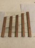
The Wharf is getting some attention. That special relationship... The formation is being solidified - not so much set in stone, as concrete. This is the third siding being relaid; the last solution was deemed too hazardous to the shunters. This gives a bit more clearance opposite more distant nose of the crossover. The engineers were very keen to use the existing 3-way, which - while saving space - does have a quite slow divergence. Apparently, it was built with the intention of running 2-10-0s through it, but Mister Holden’s Beast would never have shown its legs on the Wharf.
Cheers
Jan
Hello @jonte
I have one I can send you (I've managed to acquire 3 in my extended dalliance with all things P4-ish..). No cost.
Cheers
Jan
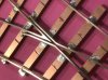
I’ve just realised from the close-up that the trackwork is inlaid - and complex. I’m off for a lie down.
Commendable stuff, Jan.
Jonte
)")


") And follow I shall (although I’ve no idea where the ‘follow’ button lies
And follow I shall (although I’ve no idea where the ‘follow’ button lies  ). Wouldn’t like to miss anything.


")