Lyndhurstman

Western Thunderer
Frame At Last
A day of less-than-100% in the health stakes, so I’ve progressed a bit more on the Nickel niceties of the PALBRICK.

The first thing to do was to make the eight triangular supports that keep the ends in place.
Their a bit fiddly, but the plate sits well on the slot designed for it. It’s just a matter of following instructions, really.
36A05911-C118-457F-AC33-D98499CDBC73.jpeg
The strengthening rib was bent up, and ever so slightly tighter than required.
A013C991-9E4C-4357-8BD0-5C6888BF9E90.jpeg
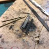
The plate was then pushed in, and solder paste applied with a sharpened cocktail stick. The assembly was then held against a vee block (yes, I’m a charlatan…) with the end of a needle file, while 25 Watts was applied using the other hand.
0CB78372-18AC-48DE-BE2C-A9B8B483CE7B.jpeg
(Naff positioning of camera is a skill I’ve had for years).
The result:
970FD7D0-5E49-4E1B-912D-DFB8EEDB6CFE.jpeg
After that, the rest of the day has been all about the adjustable end.

The frames were cut from the fret and held in my Bug Hold & Fold to get rid of extraneous tabs and burrs.
0A3B9B8B-AEF9-4E6E-8C39-400229AFBEC6.jpeg
the tricky bit here as getting the ‘screws’ to sit upright in the back of the clamping bar. The instructions recommend making the screw 25mm long, and cutting it down to 5mm required after you’ve finished. The Scrooge in me identified that as wasteful, so I went with 10 mm, a pair of tweezers, and some solder paint. I neglected to photo that bit of freehand, so you’ll have to accept it turned out OK (the fact that it was able to sit into the other holes without adjustment spoke volumes).

Once that was done, it was a straightforward matter of putting the other two bits (frame and channel - bent up in the Hold & Fold) together. This was achieved by drilling through holes in the etched components, into a piece of MDF, and putting a couple of 0.9 mm drills in the sockets as alignment dowels
6DFB74C6-482B-4C38-B270-7596710AF168.jpeg
Both parts were tinned, and soldered together. The fit with the clamp was checked again, and the ‘screws’ trimmed to their final length using a suitable mark on the MDF and transferring it to the brass:
8AF0BADF-9F23-4A08-96F8-5F0CF8E4FE42.jpeg
The palaver above was repeated for the second clamp bar:
1220136A-89AC-4391-8B68-A30ED4C6EA75.jpeg

… and that’s where we are.

Cheers

Jan
 

Attachments

  • 67E3A63F-8BE9-433F-A67C-28851B6AAD48.jpeg
    67E3A63F-8BE9-433F-A67C-28851B6AAD48.jpeg
    178.8 KB · Views: 2

Mike Garwood

Western Thunderer
Hi Ade

Into about the first third of Ian's O33 GWR siphon. Instructions are excellent, plenty of build photos to follow. Get started, what's the worst that can happen? You'll make mistakes, every modeller no matter how experienced still does. That's what makes kit building so addictive.
Plenty of threads on here show how to solder. Jump in, you will enjoy and learn more about the prototype if you do.

3 years is nothing, I've had my 9f chassis from Dave Bradwell 20 years and counting....

Stay safe

Mike
 

Lyndhurstman

Western Thunderer
Hi Ade

Into about the first third of Ian's O33 GWR siphon. Instructions are excellent, plenty of build photos to follow. Get started, what's the worst that can happen? You'll make mistakes, every modeller no matter how experienced still does. That's what makes kit building so addictive.
Plenty of threads on here show how to solder. Jump in, you will enjoy and learn more about the prototype if you do.

3 years is nothing, I've had my 9f chassis from Dave Bradwell 20 years and counting....

Stay safe

Mike
I’ll second what @Mike Garwood says, @AdeMoore. Jumping in is the best way. But I do think that you’ll know when the time is right. Enjoyment is key. And completion isn’t vital; we all have Shelf Queens that - for whatever reason -have stalled or halted. Either through personal failure or poor design (my longest-running shame is an ex-Impetus 16” Hunslet that I just couldn’t get to quarter properly; in the end I pulled the chassis apart, and it’s remained that way for a couple of decades… ).

Anyway, here’s a bit more, completed tonight. The four support brackets have been soldered in place:
0C2D3335-5088-4C4E-95FA-C9C2A31074FC.jpeg

Cheers

Jan
 

AdeMoore

Western Thunderer
Cheers all for the encouragement but if you see my WTW Jane topic you’ll see how bad I am!
I’m currently designing new baseboards for Barnstaple Quay meets Meldon.
Then on to building them, so much as your kind support is welcome the diversion wouldn’t! To my current goal.
See how I’m doing when the dark nights come.
Cheers
Ade
 

Lyndhurstman

Western Thunderer
End Dive
Lettuce continue..
The fixed end of the PALBRICK was fitted last night. Again, a very clever design; an overlay for the uprights - that have tiny feet to fit in tiny holes on the deck - and an etched representation of the wooden end board. Held upright by more buttresses.

I messed this up, a bit. Trying to get the buttresses to solder to the overlay meant that a lot of heat was generated, and it wasn’t until I’d got the last one in that I realised that the heat had caused the body to come away from the running plate, lifting up by 0.5 mm or so. So off came thr buttresses, and back on went the body… only for the ends of the overlay to become unstitched… It was a battle - hence the presence of too much solder around some of the joints - but I won out in the end. I’ll clean it up before I go any further.

DF27514D-0C2C-44B0-9CDA-A0A7FFD0E008.jpeg

Next up, the brake gear.

Cheers

Jan
 

Lyndhurstman

Western Thunderer
Stop Motion
Brakes tonight. Not much to say; the kit provides cunning mounting holes for 00 or EM/P4, and even advises those using Hornby 00 wheels that they might need to use the outer setting due to fouling. Which speaks of attention to detail and considerable research by the kit designer.

As ever with Morton’s, getting the brake actuator sloping in the right direction is always a worry; especially when you’re working upside down! Lots of turnovers (which reminds me - not long now until the NFL season returns… ).
E4739BF9-00A1-46A7-A1C1-218296606779.jpeg
I went slightly off piste wrt the instructions, by threading the brake cross shaft through both sets of rigging and the V hangers before soldering the rigging in place in their accurate and accommodating holes. This makes everything better located, I think. And easier to adjust into the vertical plane. Mind you, I haven’t put the wheels in yet…
8A7B9C2F-7992-43E3-B6B9-65C910E996A8.jpeg
… I need to do something about that skew-whiff support left of centre… I thought it was fixed…

Cheers

Jan
 

jonte

Western Thunderer
Intricate stuff, Jan, I must say and a somewhat hard fought battle at times which I’m pleased you appear to be winning!

Good to read that - most important of all - you are enjoying the experience.

Keep on keeping on!

Jonte
 

Lyndhurstman

Western Thunderer
Intricate stuff, Jan, I must say and a somewhat hard fought battle at times which I’m pleased you appear to be winning!

Good to read that - most important of all - you are enjoying the experience.

Keep on keeping on!

Jonte
Hello @jonte ,
Appearances can be deceptive But thanks for the encouragement - mightily appreciated.

as I’ve tried to highlight; it’s a well designed kit. I’ve only freestyled a couple of times as far as the instructions go.. I put the brake safety loops in last night; again, well thought out, and the only issue was the oscillations of the iron tip as a result of my physiology. Can’t blame the designer for that…

I hope you’re well. I’ve been following your permanent way trials and tribulations. I’m sure you’ll emerge victorious in the end!

Cheers

Jan
 

jonte

Western Thunderer
Hello @jonte ,
Appearances can be deceptive But thanks for the encouragement - mightily appreciated.

as I’ve tried to highlight; it’s a well designed kit. I’ve only freestyled a couple of times as far as the instructions go.. I put the brake safety loops in last night; again, well thought out, and the only issue was the oscillations of the iron tip as a result of my physiology. Can’t blame the designer for that…

I hope you’re well. I’ve been following your permanent way trials and tribulations. I’m sure you’ll emerge victorious in the end!

Cheers

Jan

Provided I’m not committed to the asylum first !

Thanks, Jan.

Jonte
 

Lyndhurstman

Western Thunderer
Dangling Over
The various verticals (brake safety loops, brake lever guard) and the duo of diagonals (brake levers) have been applied. The most pesky of pieces is the tiny figure of eight that represents the Morton clutch. The instructions warn you against swamping it with solder, and I think we’ve stayed true to that. Trying to fit the small upper pin (0.8 mm dia) into three layers (vee, lever, clutch overlay) was a strain, though. But I’m happy with what we’ve managed.
CF6458CE-E420-4A11-A777-10965B940B7B.jpeg A96666CA-F465-45AA-871D-03153EB88BC9.jpeg
Despite their incredible intricacy, I think I prefer Craig Welsh’s brake lever guards.But these are very good, and fit in a tiny slot in the foot of the solebar.

We’re closing in upon completion. Not long now…

Cheers

Jan
 

Lyndhurstman

Western Thunderer
Cast Offs

The final fittings have been attached.. or at least those that will be fixed prior to painting.. The label clip and number plate have been added to the solebar. The instructions suggest an RSU, but I managed with the thin tip of my 25W Weller. Having tinned both surfaces of
course…
AD66D8AB-02CF-424A-A5F9-EB86D891B02B.jpeg
The buffers and axleboxes have been modified to suit. The buffers were filed flat on one side to enable them to slide alongside the back of the solebar, and so sit tightly against the bufferbeam overlay, with the accommodating hole SLIGHTLY countersunk to accommodate the slight radius of the casting as it meets the back of the buffer flange.
E54C311D-1FE3-4C5E-9535-7FAE79702A26.jpeg
The axleboxes were straightforward, but the springs had to be squashed slightly in a pair of pliers in order to get them to sit between top of axlebox and bottom of solebar.
235C7EC4-6AA1-48F7-B97A-ACF341ED66CE.jpeg
The sequencing was as per instructions, here, but If it were me, I would have added the casting detail before the brake lever.

A final touch was too glue the vertical stanchion overlays in the middle of the two side boards.

Cheers

Jan
 

Lyndhurstman

Western Thunderer
Mendicant
09C0070B-4121-4F32-B90C-E66BD05EBD4C.jpeg

A failed attempt with the acrylic dooms the Cambrian 8 plank to an alternate future.

It quickly became apparent that the side plank detail wasn’t strong enough - especially towards the bottom - and my hand not steady enough, to provide individual weathers planks to the SR 8 Plank. So I changed tack, and tried to represent an unpainted wagon, that was coming to the end of a hard life (and I know that this probably never happened to ex-SR stock) and write it off as experience. Disappointing, but it’s not life or death. The painting of the metalwork with Railmatch Early Freight Grey makes a difference; at least to my dreadfully needy eyes! I shall number it, and put it deep in the stash, and move on to other things…

Cheers

Jan
 

jonte

Western Thunderer
Mendicant
View attachment 149900

A failed attempt with the acrylic dooms the Cambrian 8 plank to an alternate future.

It quickly became apparent that the side plank detail wasn’t strong enough - especially towards the bottom - and my hand not steady enough, to provide individual weathers planks to the SR 8 Plank. So I changed tack, and tried to represent an unpainted wagon, that was coming to the end of a hard life (and I know that this probably never happened to ex-SR stock) and write it off as experience. Disappointing, but it’s not life or death. The painting of the metalwork with Railmatch Early Freight Grey makes a difference; at least to my dreadfully needy eyes! I shall number it, and put it deep in the stash, and move on to other things…

Cheers

Jan

Looks like it’s on its last legs, Jan, if you would permit me to be so bold!

I do admire your worn wood tones. Mine tend towards the grey end of the spectrum, which is not always the way, especially with rolling stock. In the past, my feeble attempts ended up ‘too’ brown or another shade completely. I’m intrigued, Jan, and ‘wood’ ;)be delighted to read how you attained the effect, again, if I may be so bold :)

Good to see you back.

Jonte
 

Lyndhurstman

Western Thunderer
Looks like it’s on its last legs, Jan, if you would permit me to be so bold!

I do admire your worn wood tones. Mine tend towards the grey end of the spectrum, which is not always the way, especially with rolling stock. In the past, my feeble attempts ended up ‘too’ brown or another shade completely. I’m intrigued, Jan, and ‘wood’ ;)be delighted to read how you attained the effect, again, if I may be so bold :)

Good to see you back.

Jonte

Hello @jonte

Thank you. You’re very kind. It’s a bigger shambles than the one in York, to me.
I followed the instructions on the Lifecolor paint set, but quickly realised that - like an excursion train - it wasn’t going to work. And it wouldn’t come right (the two base coats were well dry by this point…). So I blatted it with some lighter wood tones from the kit, and set about it with a thin wash of dark grey. I tried to delineate the lower planks using a very sharp pencil, but by this point, my fingers were cramping, having been clutching at straws for so long.

I intend a fleet of life-expired wooden wagonry: various references to a cull of these beasts on the early 60s being the raison d’etre for Watkins Wharf to have a siding-full kicking about…

Thanl you again. I plod, muddy, and stumbling…

Cheers

Jan
 

jonte

Western Thunderer
Hello @jonte

Thank you. You’re very kind. It’s a bigger shambles than the one in York, to me.
I followed the instructions on the Lifecolor paint set, but quickly realised that - like an excursion train - it wasn’t going to work. And it wouldn’t come right (the two base coats were well dry by this point…). So I blatted it with some lighter wood tones from the kit, and set about it with a thin wash of dark grey. I tried to delineate the lower planks using a very sharp pencil, but by this point, my fingers were cramping, having been clutching at straws for so long.

I intend a fleet of life-expired wooden wagonry: various references to a cull of these beasts on the early 60s being the raison d’etre for Watkins Wharf to have a siding-full kicking about…

Thanl you again. I plod, muddy, and stumbling…

Cheers

Jan

I’m convinced it was intended; you’re far too humble my friend :)

Yes, a fleet would be good:thumbs:

Jonte
 

Lyndhurstman

Western Thunderer
Framing Hell

After several months hiatus, slight return to the ex-LNER Y4 for Watkins Wharf, as the tiny beginnings of the gyratory gubbins are beginning to appear on the bench.

Frames of 15 thou brass, and nickel silver coupling rods. I’ve cut both overlong to get some excess to allow me to sweat them together.
81B331BA-92DA-46EB-B689-DE383B7D482E.jpeg
The four pieces were cut with a skrawker blade - the orange handle tool top right. Although you have to be watchful that you stay in the groove (literally), for me, it beats using the piercing saw. There will be plenty of opportunity for that, later on….

The Y4s were outside Walschearts, so I’m dong all I can to minimise error in the motion. The blanks for the coupling rods are used to position the axle holes in the chassis. The frames are soldered together - using my Nimrod SolderPro gas iron; just visible at the back - and then drilled using the coupling rod centres as a guide. They will be opened out incrementally.
251BF952-2C6D-4B3C-8649-4293B91BB858.jpeg

More anon, hopefully…

Cheers

Jan
 

Lyndhurstman

Western Thunderer
Collectivism
A State Of Play post. The levels of real life in the last couple of months have meant that progress on Tiny Trains has been slow. However, it’s not been completely halted, as I hope the image below shows.
867977F7-D81A-4028-977C-6C4593B3C3C7.jpeg …apologies for the chaos of the substrate, but you should be able to see:
1 x chassis suitably bearinged.
2 x Coupling Rods, built up,
2 x Cylinder ends,
2 x motion plates,
4 x expansion die block brackets

Underneath the chassis is the overlay that will form the cylinder lagging sheet.

All these things are being built in order to fix the position of the motion. Next on the list are the slide bars, to fit a pair of Comet crossheads we had in Stores.

Once they’re made, and the wheels have been sourced (not to mention altered to conform with the half spoke / half balance weight of the original) then we can begin to think about the various links and rods that Mr Hill threw at the front end of this little beast, with due deference to Mr Egide Walschaert.

For all this positive motion (if you’ll pardon the pun) the proboscis of the elephant in the room - the fixing of the return crank to the rear driver crank pin - is always in the corner of our vision.

So that’s where we are. Still here, still trying, but channeling Arturo Bassick.

Happy New Year

Love, Light, and Peace

Jan
 

Lyndhurstman

Western Thunderer
Sent Packing
Another scattering of stuff, but mostly focused around the production of the two cylinder packing glands - that also serve to brace the slide bars at the forward end.

The glands were cut with a piercing saw from an offcut of brass I’ve had in a tobacco tin for several decades. Filed to shape with Cut 2 needle files. In the picture, the second one awaits freeing from its imprisonment.
54BB1620-A7DC-4D2A-8991-731E7B381E3D.jpeg
A few hours of piercing saw and needle file over the weekend and yesterday evening saw the completing of the pair.
1FA3B8DB-07DF-4434-A373-CCB25B87C494.jpeg
Their extrusions will - I hope - be able to be sawn slightly to accept the nickel silver slide bars I’m currently working on - and be apart enough (3.8 mm) to allow the Comet cross head to slide (but not move up and down).

Outside Admission: Due to an error in scaling (legalese for our messing up), the glands as cut are about 1 mm too thick, so I’ve spent some in time in the interim skating them along a needle fileh held down by a thumb, to reduce them to a more tolerable width.
Having started the slots for the slide bars, we thought I’d best give it a test fit, to make sure we have room. It looks OK, and - just as importantly - feels OK too.
Well have to think about soldering the crosshead arm onto the crosshead. Lost wax castings… and the soldering thereof… And trying to make a union link 4mm long (holes at both ends). Fun times…
238E6AD0-7EFF-4D68-B286-EB61FC23A912.jpeg

Cheers

Jan
 
Top