paratom
Western Thunderer
I have posted this topic on RMWEB but thought I would post here as well to see if the replies are similar to the ones I had on RMWEB
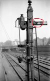
I am creating some 3D printed parts for a MR lower quadrant signal as some of these parts are no longer available from Wizard Models. I believe the back blinder had the job of not allowing any light from the signal not to be projected backwards and to cause confusion for drivers who were not familiar with the route. I can't see how light could have been seen from the back of the signal lamp as the lens was in the front but maybe I am missing something here. Did this also apply to ground signals as well ? I assume the circled in red on the photo is an arm repeater contact box. As an experiment I'm going to try and light the signal lamp that will be 3D printed out in clear resin with a recess for a .5mm LED feeding the wires up through the inside of the signal post and through the side into the signal lamp. I've often thought it would be nice to be able operate a layout in a night time setting as it can be quite atmospheric if you use the right light. I would be most grateful for any replies.
I am creating some 3D printed parts for a MR lower quadrant signal as some of these parts are no longer available from Wizard Models. I believe the back blinder had the job of not allowing any light from the signal not to be projected backwards and to cause confusion for drivers who were not familiar with the route. I can't see how light could have been seen from the back of the signal lamp as the lens was in the front but maybe I am missing something here. Did this also apply to ground signals as well ? I assume the circled in red on the photo is an arm repeater contact box. As an experiment I'm going to try and light the signal lamp that will be 3D printed out in clear resin with a recess for a .5mm LED feeding the wires up through the inside of the signal post and through the side into the signal lamp. I've often thought it would be nice to be able operate a layout in a night time setting as it can be quite atmospheric if you use the right light. I would be most grateful for any replies.

