Crimson Rambler
Western Thunderer
Having returned to modelling (S7) after a long break – spent playing with horses and writing locomotive books – I have started building my train set – late ‘nineties Midland Railway with only one planned anomaly (so far) – a Belpaire. Started in earnest just over two years ago with laying out the track plan in AutoCAD – four track London Extension – sort of.
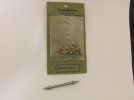
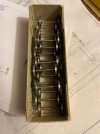
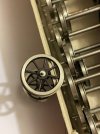
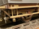
I was involved last summer in helping a friend (who posts in a rival vineyard, one that I’m sure you will be familiar with) in the forum Pre-grouping – Modelling and Prototype – Midland Railway Company with his S7 Midland locomotive shed layout inspired by Hellifield. My primary task was to produce some functional point and crossing chair masters for him which later would also be used by me. I posted a few photos in September last year of some of these chairs on the WT forum Hartley Hills LNWR c1900 but because I don’t know how to put in a link from here to there, some are repeated below, they are all 85lbs outside key.

1 in 10 common crossing

1 in 5 common crossing

1 in 8 diamond crossing
Before making the additional chair masters that I will need, I decided to attempt the bit of modelling I most enjoy – locomotive building. However, not having used a file or a pin vice or a soldering iron etc in anger for so long I was concerned that I had lost what little form I had so I decided to start with a few etched locomotive kits before resuming scratchbuilding. Unfortunately, one trait I certainly have not lost during the break is a complete inability to build a kit without throwing away many of the bits away - either replacing them or at the very least modifying them.
The initial recipient of my attentions is a Class N 0-6-0T which while theoretically being built from the Slater’s kit is but the latest example of this approach. When Ian Rice observed in his book on etched locomotive construction there is a difference between building locomotive kits and building locomotives from kits, he summed up my approach in a nutshell.
When finished it will be No. 1997 because this was allocated to Wellingborough when new. It moved away after a few years but I suspect that No. 1997 was the only one of that batch that stood any chance of getting south of Bedford but if I’m honest it is pretty remote one at best. It also means it can be finished in the Vulcan Foundry’s version of Midland livery as worn in the photo of sister engine No. 2012 that appears in Jack Braithwaite’s book – assuming I can get someone to paint it for me.

Here are a few photos shewing some of the progress to date. These 0-6-0s were built with separate horn guides rather than hornblocks so after the frames had been separated in order that they can be spaced the scale distance apart 4ft – 2ins or to scale 1148 thou, I modified the design that came with the kit. The folded top hat section was discarded and instead a set of the cast Slaters hornblocks substituted save they were cut up to form separate horn guides thereby giving something more reminiscent of the prototype.

Using Imperial dimensions is another approach I have retained, in conjunction with marking out for example using a scale rule. One pair of pick-up holes have had to be added to each frame between the crank axle and the trailing axle – the original ones will be plugged.

Revised motion plate – awaiting valve spindle guides along with levelling up the holes – together with the front and back of the cylinder ‘block’. The latter is made mostly from salvaged etch material. The original intention was to cut away the rear corners of the cylinder fabrication to clear the leading horn guides but by the time I realized that was going to be a bit difficult given the way I had designed it the horns were soldered in place. So instead I have followed the prototype and cut the latter to suit. There’s a moral there somewhere.

Rear frame spacers which together form the dragbox under the bunker with the lower one carrying the toolbox. The latter is offset to clear the handbrake. After soldering they were put in the ultrasonic cleaner – a new toy – which promptly dislodged one of the door hinges. The corners of the frame spacers should be angled at 45° but I haven’t bothered – this engine was after all meant to be a ‘quickie’ to get me back into the swing of things! Famous last words!
Thus, originally, I wasn’t going to bother with bolt and rivet detail hence its absence on the cylinders but that sort of got forgotten by the time I renewed the buffer beams - drilling the different hole patterns between the front and back! Front on the left, rear on the right. Now it’s sort of progressed to add the bolt and rivet detail if its ‘noticeable’!

The ashpan has been widened to scale width using the etched one-piece front, top and rear plate cut in two as an armature. Unfortunately, I didn’t notice when I made the new ends and wrapper that the original ends were too shallow – while debating how to cobble something together or simply to scrap it and make a new one I wandered elsewhere making other parts. But before I sign off here is the platform with its revamped smokebox.

When I bought the kit, I arranged for it to be sans boiler – the hassle of rolling a replacement boiler from thin sheet and sorting out the cladding bands far more enjoyable than trying to solder that massive heat sink aka the kettle that form part of the standard kit. I have started to modify the cab opening in line with the prototype – presumably done to avoid the crew barking their shins – for some reason the step plate was set further back on the Class N and a few other batches of these tanks.
Quite a few other parts have been made but they are just that. Hopefully despite my other commitments – oh the joys of still working even through the current covid business – it will not be too long before I have assembled some of these into bits that are recognizably ‘locomotive’.
Crimson Rambler
I was involved last summer in helping a friend (who posts in a rival vineyard, one that I’m sure you will be familiar with) in the forum Pre-grouping – Modelling and Prototype – Midland Railway Company with his S7 Midland locomotive shed layout inspired by Hellifield. My primary task was to produce some functional point and crossing chair masters for him which later would also be used by me. I posted a few photos in September last year of some of these chairs on the WT forum Hartley Hills LNWR c1900 but because I don’t know how to put in a link from here to there, some are repeated below, they are all 85lbs outside key.
1 in 10 common crossing

1 in 5 common crossing
1 in 8 diamond crossing
Before making the additional chair masters that I will need, I decided to attempt the bit of modelling I most enjoy – locomotive building. However, not having used a file or a pin vice or a soldering iron etc in anger for so long I was concerned that I had lost what little form I had so I decided to start with a few etched locomotive kits before resuming scratchbuilding. Unfortunately, one trait I certainly have not lost during the break is a complete inability to build a kit without throwing away many of the bits away - either replacing them or at the very least modifying them.
The initial recipient of my attentions is a Class N 0-6-0T which while theoretically being built from the Slater’s kit is but the latest example of this approach. When Ian Rice observed in his book on etched locomotive construction there is a difference between building locomotive kits and building locomotives from kits, he summed up my approach in a nutshell.
When finished it will be No. 1997 because this was allocated to Wellingborough when new. It moved away after a few years but I suspect that No. 1997 was the only one of that batch that stood any chance of getting south of Bedford but if I’m honest it is pretty remote one at best. It also means it can be finished in the Vulcan Foundry’s version of Midland livery as worn in the photo of sister engine No. 2012 that appears in Jack Braithwaite’s book – assuming I can get someone to paint it for me.

Here are a few photos shewing some of the progress to date. These 0-6-0s were built with separate horn guides rather than hornblocks so after the frames had been separated in order that they can be spaced the scale distance apart 4ft – 2ins or to scale 1148 thou, I modified the design that came with the kit. The folded top hat section was discarded and instead a set of the cast Slaters hornblocks substituted save they were cut up to form separate horn guides thereby giving something more reminiscent of the prototype.
Using Imperial dimensions is another approach I have retained, in conjunction with marking out for example using a scale rule. One pair of pick-up holes have had to be added to each frame between the crank axle and the trailing axle – the original ones will be plugged.

Revised motion plate – awaiting valve spindle guides along with levelling up the holes – together with the front and back of the cylinder ‘block’. The latter is made mostly from salvaged etch material. The original intention was to cut away the rear corners of the cylinder fabrication to clear the leading horn guides but by the time I realized that was going to be a bit difficult given the way I had designed it the horns were soldered in place. So instead I have followed the prototype and cut the latter to suit. There’s a moral there somewhere.

Rear frame spacers which together form the dragbox under the bunker with the lower one carrying the toolbox. The latter is offset to clear the handbrake. After soldering they were put in the ultrasonic cleaner – a new toy – which promptly dislodged one of the door hinges. The corners of the frame spacers should be angled at 45° but I haven’t bothered – this engine was after all meant to be a ‘quickie’ to get me back into the swing of things! Famous last words!
Thus, originally, I wasn’t going to bother with bolt and rivet detail hence its absence on the cylinders but that sort of got forgotten by the time I renewed the buffer beams - drilling the different hole patterns between the front and back! Front on the left, rear on the right. Now it’s sort of progressed to add the bolt and rivet detail if its ‘noticeable’!
The ashpan has been widened to scale width using the etched one-piece front, top and rear plate cut in two as an armature. Unfortunately, I didn’t notice when I made the new ends and wrapper that the original ends were too shallow – while debating how to cobble something together or simply to scrap it and make a new one I wandered elsewhere making other parts. But before I sign off here is the platform with its revamped smokebox.
When I bought the kit, I arranged for it to be sans boiler – the hassle of rolling a replacement boiler from thin sheet and sorting out the cladding bands far more enjoyable than trying to solder that massive heat sink aka the kettle that form part of the standard kit. I have started to modify the cab opening in line with the prototype – presumably done to avoid the crew barking their shins – for some reason the step plate was set further back on the Class N and a few other batches of these tanks.
Quite a few other parts have been made but they are just that. Hopefully despite my other commitments – oh the joys of still working even through the current covid business – it will not be too long before I have assembled some of these into bits that are recognizably ‘locomotive’.
Crimson Rambler


