Nick Dunhill's Workbench - Pair of EM2s

Nick Dunhill

Western Thunderer
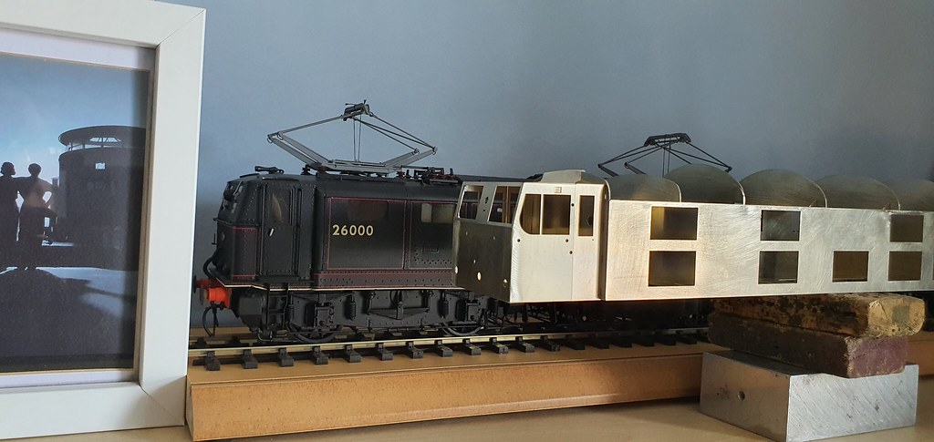
I was asked to build a pair of EM2s from MSL Hobbies kits. I was delighted as I have lived in Manchester, Sheffield and Rotherham all my life and was/am a big fan of Woodhead and especially the electric locos.

One of the supplied kits was in pristine condition, still in the box with all of the original packing, the other had been opened and fiddled with, and some of the etchings had been damaged at some point. I contacted Mick Davies (Mickoo) who agreed to produce some etchings to replace the badly damaged ones in the kit. It occurred to me that perhaps we should make 2 sets of etches so that both models match each other. Of course the project developed a life of it's own at this stage and Mick actually produced 2 complete bodies with 3D printed parts, more of which later.

52154942988_a0345c82b4_b.jpg


52153926307_db7c5100cf_b.jpg


Better than any steam loco, including Kings, A4s and Princess Coronations.

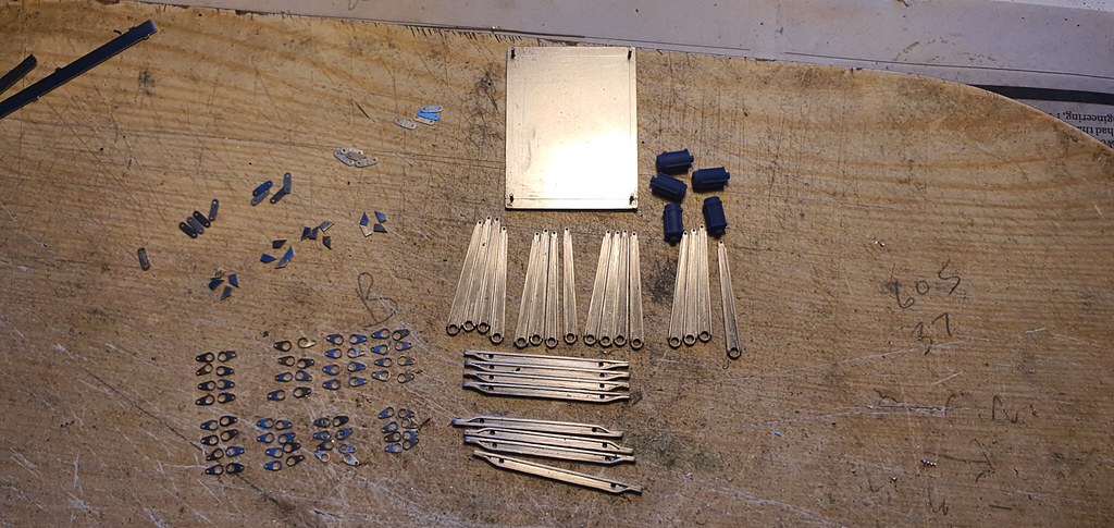
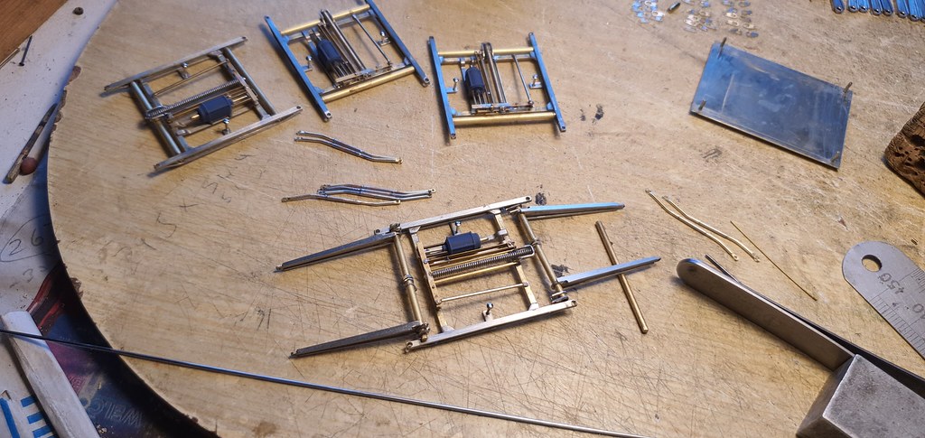
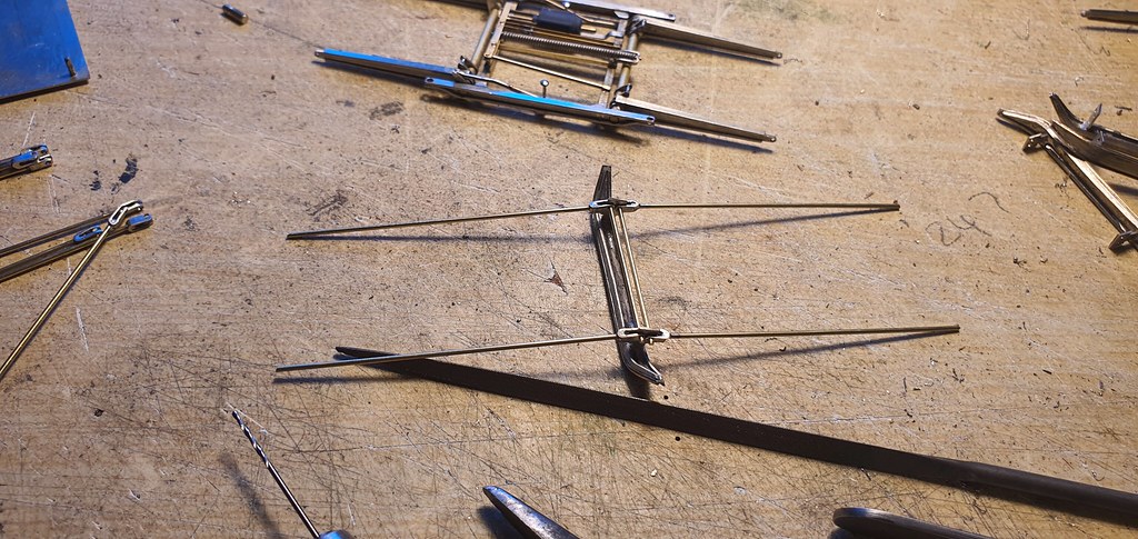
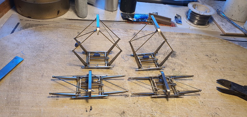
I figured that if Mick produced the body etches I could scratchbuild my way round the rest. The EM2 bogies are the same as those fitted to the LMS pioneer locos 10000 and 10001 and MM1 Models agreed to sell me 2 pairs from their kits. I had some pantographs drawn by Adrian Rowland years ago when I scratchbuilt a model of Tommy (EM1 prototype,) and luckily PPD still had the photo etch tool!

The etched body panels arrived from PPD Ltd. One pair of panels had the skeletons of the bodies in nickel-silver and the other pair were brass overlays of all the rivet and strapping detail.

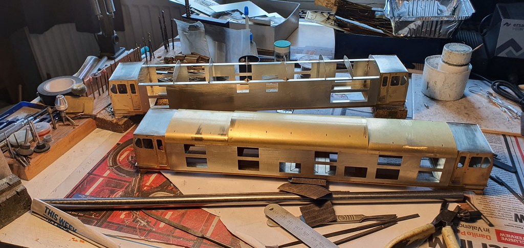
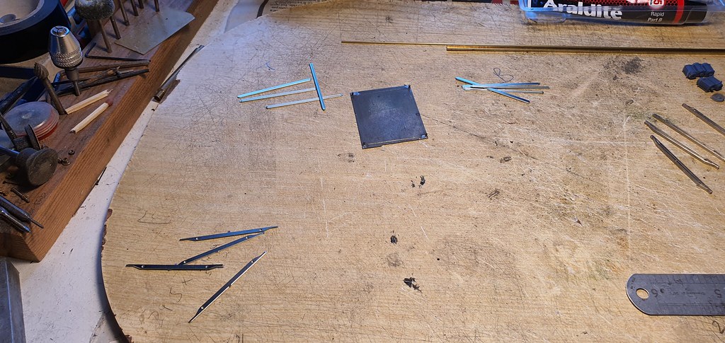
I began by building the bodies. The sides were folded up from the floor after the cantrail rib had been folded at a right angle to the side, bulkheads/formers were installed and the cab rears folded up. The last sentence makes the process sound simple, infact it is feindishly difficult. The fold lines have to be heavily scored to emphasise them, and even then the strips above and below window and louvre appertures bellied out on folding. These had to be encouraged using itterative folding and a hammer to straighten the bellied parts. I used a rectangular dolly to the rear to reshape the sides around the folds and the appertures. I used an actual hammer to build an O gauge loco. The structure has to be constantly checked for squareness and straightness and adjusted where necessary. It has to be able to sit flat on a flatbed and all she sides and ends have to be square and straight.

Next the cabs were folded, and again squareness is paramount! The cabs were then attached to the bodies, I did this on a flat piece of plate glass to make sure the whole thing is true. Again it has to be spot on!

52154998434_0f806a718d_b.jpg


And here are the cabs taped to the bodies prior to fixing. You can see that I've attached the roof ribs.

52155420425_63afc038f2_b.jpg


52155170004_374942198f_b.jpg


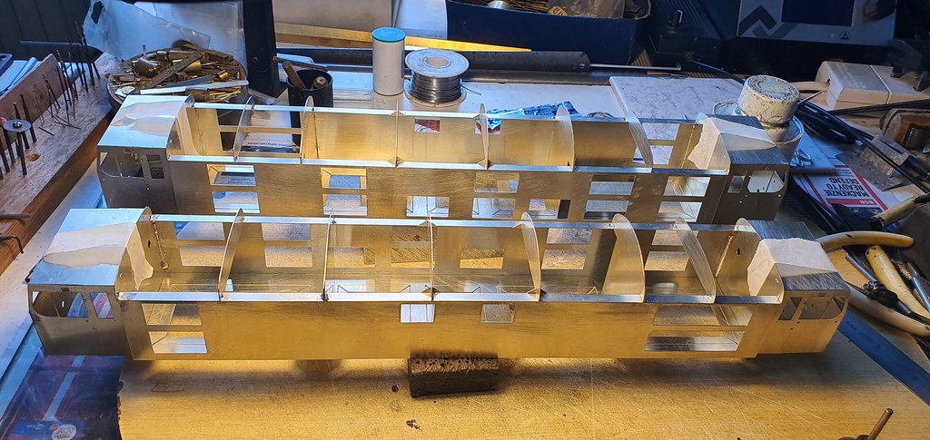
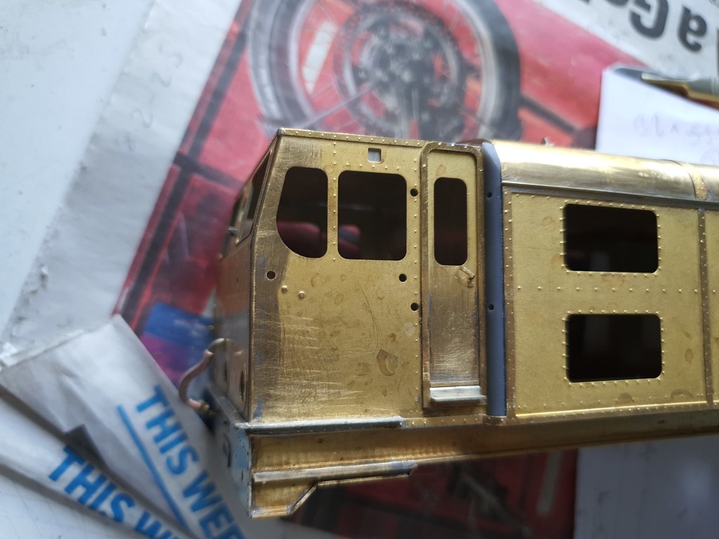
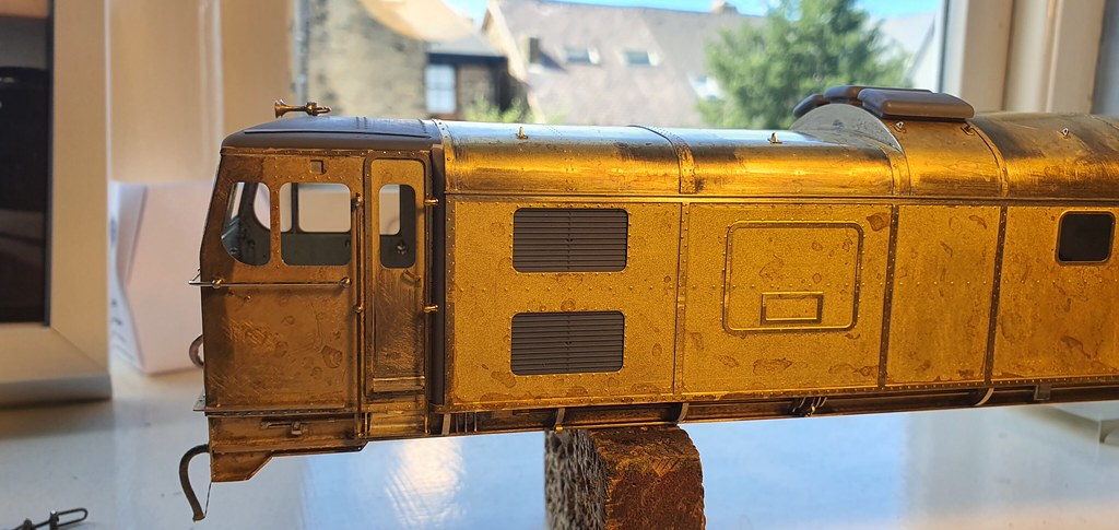
The process of attaching the overlays then began with the cabs. Much care is needed to align everything then radius the cab corners.

52155420650_2e5d62f07e_b.jpg


Then a deep breath and form the roof sections. They must be very close to the correct shape before attaching. You cannot use the roof ribs as formers as you will leave a witness mark on the outside.

52155169919_0f8db114cf_b.jpg


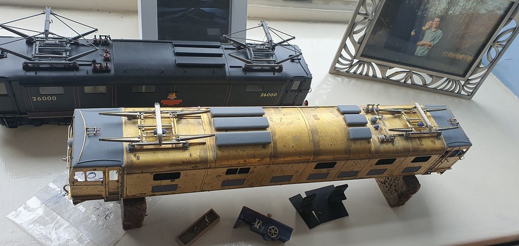
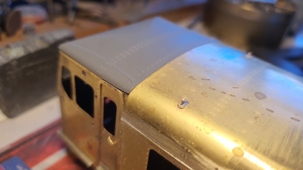
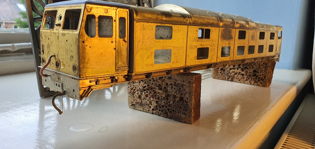
Lastly the body side overlays can go on. This is the bit where you find out how accurate your fabrication has been. The side overlays have a rebate alont the inside of the top edge that slides satisfyingly over the bottom edges of the roof to disguise it all. I soldered the sides on using 90 deg solder with my iron tip temp turned down a bit to prevent any heat buckling.

52153920622_61bc3f42ab_b.jpg


You can see in the above picture that I have added some door details and all the lifting lugs on the roof. There are many many repeats. I also scratchbuilt the solebars and buffer beams. The solebars are cut from 6 x 2 mm brass L-section from Phil Atkinson at Hobby Holidays.

I've built quite a few models of steam locos but building deisel and electric locos is much more difficult because of the accuracy required.

There's a few more pics here; nick dunhill Next week I will do battle with some 3D printed parts.
 

Nick Dunhill

Western Thunderer
This week has flown by, and much was done, but at first glance so little has changed! First up I sweated the remaining pair of body overlays on to the second model and then turned my attention to the rivet strips that cross the roof sections. The strips were quite tricky to attach so that they sat nicely on the roof sections and were straight. Also it's a test of how accurately the bodies have been made, as the strips start and end above opposite bulkhead joins on the body sides, and if the sides aren't in line the strips will not be straight. They were soldered with 70 deg solder to prevent any distortion. Door treads and handles were made and attached.

After hours of task-avoidance I decided that I had to attach some resin 3D printed parts. Working in plastic is outside my area of comfort (see my blog on building DA Princess Royals with resin fireboxes!) I needn't have worried as the parts had been printed with such care and accuracy that it was like working with Lego (with a bit of filler.) Thanks Mick.

I attached the infill pieces between the rear of the cab door frames and the body sides. They have a sacrificial edge that has to be carefully sanded back such that the outside edge of the strips land just below the body sides. There's a brass strip that curls round them at the bottom which actually serve to hold the plastic parts while the glue sets. On the advice of Mick I used 15 min epoxy resin.

52172049984_33ae2cf64e_b.jpg


The top part of the infill strips can then be profiled to match the roof. I did this with a sanding disc, keeping it parallel to the roof panel and making light passes until the disc gently touches the brass roof. The cab roofs were also 3D printed and a few trial items had passed between Suffolk and Yorkshire until we were satisfied we had a good fit. Again the cab rood sections have a sacrificial edge that has to be reduced gradually until the roof sits in line with the brass sections.

52171323908_394abdd752_b.jpg


You can see that this sits a little proud so with a bit of sanding

52171323973_4b4267cf4a_b.jpg


It can be made to sit nicely. I glued them in place with epoxy and held them with elastic bands while the glue set overnight. To fill any gaps, and blend in, I used a fine filler from a car spares shop (sold for filling stone chips and scratches.) I allowed that to cure overnight and blended it in with 240 grit wet-or-dry and lots of water.

52171800910_101794f32c_b.jpg


52171324118_6494294fa8_b.jpg


As you can see above there's a brass strip along the join between plastic and brass roof which will hide any suggestion of a join.

I made 4 sets of BR screw link couplings from LGM. They look great but take a good while to make. A U-shape of brass rod keeps them vertical in the coupling pockets. I also bought some steam loco vacuum brake pipes from LGM and they were much too short for this application. I canabalised them for the end fittings and scratchbuilt the rest by winding fine copper wire (from inside 12V motorcycle loom cable) round pre formed 12 mm brass rod.

The next little awkward job was the gutter strips at cantrail level. This is made from 0.4 mm rod planted on the top edge of the body side. I made a tool to locate the rod and allow me to tack it in place. The same tool was used to hold the rod while soldering it in place. I used 70deg solder and reduced the heat of the tip of my iron. This reduces the tendancy of the rod to try and escape by expansion. They have to be dead straight or your eye just goes straight to any distortion.

52171800595_cafdafec1b_b.jpg


52171800620_f6dccdf481_b.jpg


52171799136_f6fb20ed41_b.jpg


You can see from the last photo that the week concluded with making some of the many outriggers on the solebars. This will continue long into next week as there's dozens and dozens of them, and they're all hand cut from brass sheet. So next week when the solebar detail is done I have to fit the handrails, lamps and louvred panels. Then the bodies are done. I'll just need to add interiors, bogies and Pantographs.

More pics here nick dunhill
 

Nick Dunhill

Western Thunderer
So this week has disappeared in a frenzy of solebar detail. I have hand cut 90-odd outriggers and soldered them all to the solebars. I have discovered that there are many different shapes, some repeat many times and some are different on both sides. Some have holes in them for the runs of pipework. I have stared and stared at dozens of photos of EM2s to work it all out. Luckily they're all quite similar. I also fitted up 3 cab roofs, and added all the runs of pipework.

52186556476_f6f27a24f2_b.jpg


52187042035_1c84249db2_b.jpg


52186556761_e6bd7b1c13_b.jpg


52185536492_9572532310_b.jpg


Such a lot of work condensed into a paragraph of words. I really am enjoying the build though, even if scratchbuilding in MI is a series of many repeats. More pics here; nick dunhill

Next week it's the cab steps and handrails. Then the louvred panels, vents and lighting. Hopefully a bit of pantograph action too.
 

Nick Dunhill

Western Thunderer
Not a great deal done ths week as I had 3 tank locos across the bench for mechanical repairs and DCC upgrades. I did however sort out the cab steps and handrails. The steps are scratchbuilt from 0.3 mm nickel-silver strip.

52202937757_02bf11e8af_b.jpg


You can see that the door handrails are cranked at the bottom and not centred on the door frames, as per prototype (see pic above.) The picture also shows the handrails round the cab front, these are in nickel-silver and removable for paint. As far as I can make out the cab door handrails were black (in lined green era) and the cab front handrails polished steel or chrome.

52204465825_3f08b71b10_b.jpg


I also added the 3D printed vents ont the top of the roof. Crude 'handrails' were soldered to the roof below the vents for the glue to grab. You can still see the faint pencil lines I drew to position the 'handrails' and then vents. Positions were taken from this pic using the trusty eye-crometer.

52203983978_0dc4e4d5aa_b.jpg


Finally this week I made some horns. They are from the Markits range via Roxey Mouldings. The horns as supplied were too long so were cut up and mounted on scratch built bases.

52204228549_7723141fc8_b.jpg


Pantographs next week, surely? More pics here; nick dunhill
 

Tim Humphreys ex Mudhen

Western Thunderer
Hi Mick,

My mistake I thought you were referring to all locos in green or blue rather than only EM2. The photos that Paul has posted a link to show the front handrails on a green loco, 27000, looking very light.

atb
Tim
 

mickoo

Western Thunderer
Hi Mick,

My mistake I thought you were referring to all locos in green or blue rather than only EM2. The photos that Paul has posted a link to show the front handrails on a green loco, 27000, looking very light.

atb
Tim
;):thumbs: 
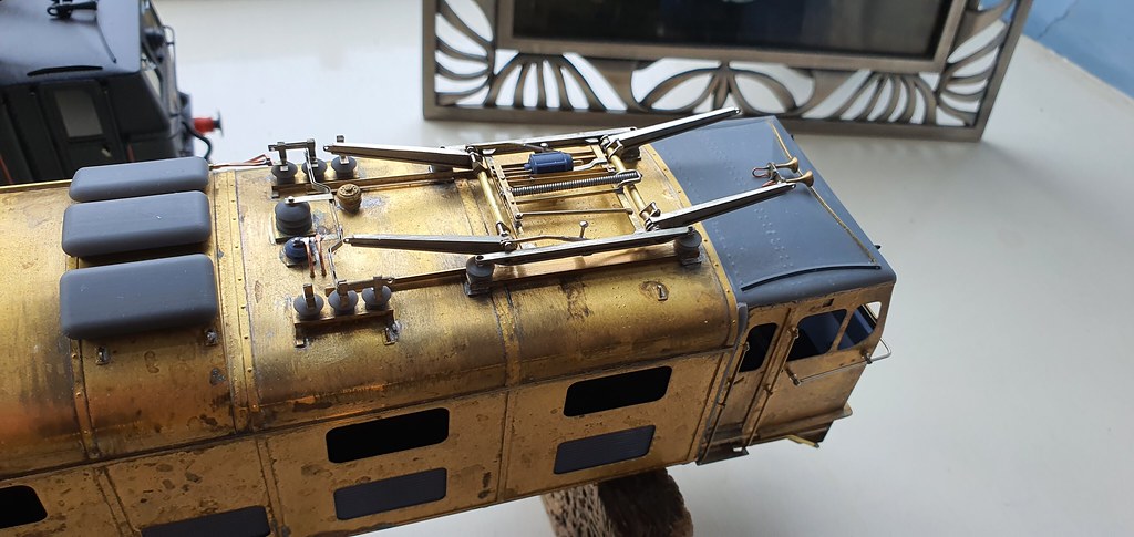
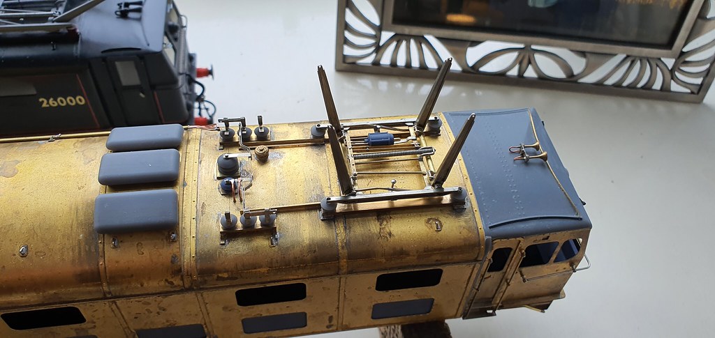
The EM2 appears to buck the norm, they were chrome but then painted and over time and use would wear, so it's reasonable to expect some areas to wear through and shown the chrome below. The knobs would remain green but the handrail might wear through through use.

What is interesting is that the cab door rails never appear to wear, only the cab front one.

Factory fresh they will be painted electric blue or Brunswick green but will not be all polished like the black engines.

If you look closely at Pauls image it can be seen they are green but chipped.

Here's a factory fresh electric blue


And a clean green one, copyright unknown

E27000_Manchester.jpg

The cab front ones are certainly brighter, possibly due to the suns high angle, but then so is the foot step around the cab base which we know is green.

MD
 
Last edited:

Lancastrian

Western Thunderer
Factory fresh they will be painted electric blue or Brunswick green but will not be all polished like the black engines.

MD
No, no, no, no, no ! Brunswick green was only used on those locomotives which were two-tone green; Sherwood green being the lighter shade. The standard BR locomotive green (steam and diesels) was Deep Bronze Green, BS381C-224, the same as that used by Land Rover, LRC001.

Ian
 

Nick Dunhill

Western Thunderer
Right. So this week I came across the first detail difference between both locos. The rain strips on the front of the cab roof are different. Minerva doesn't have any in the period I am modelling and Electra does.

52220685806_17a721c515_b.jpg


Both locos got the horns.

I made some blowers for the outer compartments of the bodies. They're made from plastic card from a well known Derbyshire supplier, and they're quite basic, but you really can't see much (if anything) of them through the windows. I made the compartment partitions from plastic card, as well as the corridor wall, with sliding doors, that passes along one side of the body. I like putting partitions and floors in model diesels and electrics. It really gives a model some heft if you can't see the track through the windows and it looks like the compartments are full of something. I made a representation of the racks that hold all the LT and HT switchgear in their respective compartments, but again they're not really visible through the windows.

52220700843_f22c838e29_b.jpg


I was about to glue it all in place and the postie came with a box of 3D Lego. I set about adding the grills/louvred panels to the body sides, as they're much easier to locate while the bodies are empty. They have a clever design and slot into windows in the inner etched skeleton. Now I was a bit worried about them distorting in the searing 40deg C Sheffield heat while I shivered on holiday in the Orkney Islands so I decided to solder them into place like this;

52220700873_ea67abd7c6_b.jpg


52220701043_1749359846_b.jpg


In this way they can be moved about a bit to align them and finally glue them as well. Hope they've not gone curly when I get home. They look like this, and I was very pleased with them so big thanks to Mick Davies for the prints.

52220954594_59bbce9481_b.jpg


52220686766_7632caa304_b.jpg


52220701858_f3ceee3932_b.jpg


You can (not) see the interior in the last pic.

I started fitting some detail to the printed control desks but had to stop to dash to get the ferry. More next time when I'll finally get to build the pantographs (or will I?) More pics here; nick dunhill

52220955354_0f6c59c78b_b.jpg


52221241685_0177d73e7a_b.jpg


Can you see the Old Man of Hoy?
 

Overseer

Western Thunderer
Can you see the Old Man of Hoy?
Yes. I have photographs taken from the top of the cliffs above the Old Man of Hoy with the ferry in the background. Reminds me of camping next to one of the beaches on Hoy, woke up to a sunny, still morning then had to grab the tent and run to try to escape the millions of midges. Wind is your friend in summer in Orkney.

Have a good break.
 

Nick Dunhill

Western Thunderer
So only a short working week this time and not much to show but I did finish the control desk.

52249512131_4ece4ec8a9_b.jpg


All the levers and stuff come off for paint. I also made some seat bases and squabs and fitted them to the cab floors. The cabs were completed by adding the lights, or not in the case of the lower lights, as the painter asked me to leave them off to make masking up easier.

52249527908_52db3905c9_b.jpg


Quite by luck the front side handrail knob shafts pin the control desk into the cab. I added the windscreen wipers as well. They're spares for a Heljan diesel, class 47 as I remember.

52248538997_4f8ef27a1f_b.jpg


And finally here are the etched and 3D printed parts for the pantographs. That's right folks, next week is panto week.

52248538792_7d398afb4d_b.jpg


52249528193_88e280bc91_b.jpg


The last pic is surely the dullest photo ever posted. More pics here: nick dunhill
 

Nick Dunhill

Western Thunderer
So this week has been spent sorting out the roof brackets for the switch gear and pantographs and busbars. All the brackets are scratchbuilt from brass sections and the printy bits are grey.

52265118663_c003d2c864_b.jpg


52265371079_200aa414b2_b.jpg


I made a jig for locating the pantograph brackets, I can use it upside down to build the pans on.

52265118548_d35a778ed6_b.jpg


All the switches and busbars are made from boiler band etch. most are 2 ply but the switch terminals 3 ply.

52265370784_3786958d75_b.jpg


52265104511_4bece4a708_b.jpg


52265104516_4e8a6b041d_b.jpg


All the insulators and busbars come off for painting. More pics here nick dunhill
 

Nick Dunhill

Western Thunderer
It's panto time! Ooooooh behind you!

I had some etched parts made 20 years ago for pans for a model of the EM1 prototype 'Tommy,' there's glimpses of it above. The etches are for the base, the lower arms and the skate, the rest has to be scratchbuilt.

52279320165_237720cff3_b.jpg


You can see in the above picture that I made up most of the etched parts and cut out a load of others. The lower arms have cranks from which both the springs and the reach rods (that make the lower arms work as a Watts Link, and therefore rise and lower together) attach. I had to make 64 identical ones.

The jig that I made for locating the roof mounts was used to fabricate the pan bases. The sides were mounted in the jig (the mounting hole positions have to be very carefully measured) stretchers were added and the shafts for the lower arms added. The shafts are 1.8 mm OD thin walled tube rotating on 1.6 mm rod.

52277857107_b3df6b1499_b.jpg


52277857037_9c644ef9b4_b.jpg


Theres a lot of bracing and mounts for the pantograph lowering mechanism. It sits on the base of the panto and is made from boiler band strips, angle and rod.

52279105879_2b0e57ecfc_b.jpg


52279105654_4924d3c7d0_b.jpg


52279319835_6a2ba87e88_b.jpg


The last pic shows one of the air cylinders fitted up that raise and lower the pan. They're printy parts, cheers angain Michael!

More pics here nick dunhill

Short week this time. By the time you read this I'll be in a sweaty car bound for a campsite in Robin Hood's Bay........oh no you won't.....oh yes I will.
 

Nick Dunhill

Western Thunderer
The pan saga continues into week 3. The first picture shows the reach rods for the Watts Links that move each pair of arms together. I made them on a simple jig. Either ends telescope inside some brass tube to maintain the correct centres.

52296639708_ffcacc1973_b.jpg


52295650872_4258af5898_b.jpg


The second pic shows all the cranks and rods and arms threaded onto the rotating shafts on the pantograph bases ready for alignment and soldering. The bell cranks for the Watts Links were aligned using my trusty eyecrometer.

52296900594_55b08436c2_b.jpg


52296900584_79cfdfce14_b.jpg


The next two pictures show the completed pan base in the lowered and raised positions. The bit of video demonstrates how the Watts Link makes the arms move in sync.


The last couple of days have been spent making the upper arms from 0.8 mm rod and the skate.

52296636281_7ba925fa7b_b.jpg


52296639323_4504ac3225_b.jpg


And here are the nearly complete pans. They need something fabricating to keep the skate level and a bit of wiring.

52296900159_f893fc2238_b.jpg


52295650372_0965c0de67_b.jpg


More pics here nick dunhill

I wonder if anyone can help me finish the models? I had intended to use MM1 Models 10,000 and 10,001 diesel bogies on these locos, they are identical to the bogies fitted to EM2s. However MM1 aren't trading at the moment as Laurie L is ill (get well soon mate!) Does anyone have 2 pairs of (unmade) JLTRT or MM1 10000/10001 bogies I could borrow until Laurie is up and running and I can get replacements for you? PM me if you can help, Ta.
 
Top