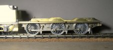
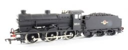
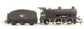
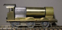
Q Class in EM Gauge from the Crownline Conversion Kit for the Airfix 4F

Stevers

Western Thunderer
This saga started when I spotted an Ebay listing for this kit. The kit seemed to hold immense potential, but I missed out on it by not bidding. A few weeks later it was relisted as a 'Buy it Now', and I quickly made sure it was mine. My model of Verwood doesn't need a Q Class for weekday services, but they were used on Saturdays in High Summer to haul Welsh miners and their families to the seaside at Bournemouth in exotic looking specials formed of long rakes of Midland and Western Region coaches.

There is a thread on RMWeb that speculated on the possibilities of making a Q out of a 4F and I started to document my build about half way down page 2.
Conversion kit for Airfix 4F to Maunsell Q

Eventually I become conscious that what had become a full-on finescale EM Gauge loco build was looking increasingly out of place in the 'Modellers Questions' part of RMWeb! So I propose to continue my build here.

P8010280.JPG
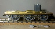
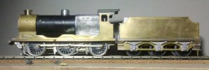
This is the current state of play with the Crownline body mounted on an adapted SEF 4F chassis ready to receive hornblocks, equalising beams and wheels. The tender has been built and is mounted on a twin beam compensated Comet chassis. In my conversion the only part of the Airfix 4F retained is the boiler, smokebox, backhead and cab floor.
 

AJC

Western Thunderer
Hello Steve, great to see this here, I’m really impressed with how it’s coming together (the Q being a favourite prototype notwithstanding). Welcome!

Adam

PS - I’ve left some wheels for you with Dad.
 

Stevers

Western Thunderer
Hello Adam,
Thanks for the wheels and welcome. I really like the Q and the chance for me to build one that really does look like one was too good a chance to turn down. With the requirement for Covid tests withdrawn I shall resume visits to YMRG HQ, and hopefully see your Dad there.
P8010281.JPG
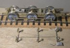
What RMWeb don't know is that there are now sets of hornblocks, coupling rods and Romford wheels for the build. The Romfords came off the 00 Gauge Jidenco Black Motor that I bought and fitted a new EM chassis to. They needed the old style crankpins drilled out and retapped and then the flanges re-profiled in my mini-drill. I'm expecting to only use them until the chassis is painted. I didn't know that they came with and without weights. The original builder of the Black Motor didn't know either and just randomly distributed them on the loco! The articulated coupling rods are the second attempt after my 22xx chassis (not) faux pas. The middle hornblocks are thinned to give room for gearbox sideplay. I'd like to put a beam across the rear hornblocks for the third suspension point, and there is a cunning plan to keep it in place when lifted off the track.
It might be on wheels by the end of today!
 

AJC

Western Thunderer
I remembered that I saw quite a bit of 30541 at the Bluebell a couple of years ago - they keep it very clean which makes it a swine to photograph - but it's probably at this stage to ask about the difficult bit - any thoughts about the all too visible motion? It's not quite as visible as a 2251 but it's pretty clear to see.

30541_Motion.jpg

Adam
 

Stevers

Western Thunderer
Thanks Adam, That's a really useful photo , and yes it has occurred to me that I need some representation of the valve gear. This is intended to be a layout loco - generally viewed side on, and not many prototype photos show any sign of inside valve gear, but yes I know it's there! It was I believe Stephenson Link, so nothing out of the ordinary. Some sort of lost wax casting that I could fasten to the smokebox saddle would be a start. With the gearbox on the centre axle no prospect of working valve gear, and my original thought was to make a bit of a feature of the twin equalising beams by painting them red - at least they're tucked away at the side potentially leaving room for valve gear. That photo also highlights that little group of four enormous rivets that I really should have added to the rear of the Crownline smokebox wrapper each side when it would have been straightforward.

For mere mortals working in 4mm, there is no chance of reproducing everything on the real thing, so a model that looks as good as the latest products of Messrs Bachmann and Hornby is my aim, but with the intention that it will be less compromised below the running plate and the certain knowledge that it will run more smoothly due to the compensation. Ideas for how best to do represent the valve gear welcomed...
 

Stevers

Western Thunderer
The chassis is all soldered together and the hornblocks fitted, and yes it's on its wheels, but with the benefit of hindsight I really, really should have opened out the cutouts for the hornblocks at the bottom. The good news is that the loco is level and a gnat's whisker off the correct ride height (a fraction low), and the wheels line up with the splashers perfectly with just a little room to spare. The bad news is that there's no scope for any of the hornblocks to drop to let those on the other end of the beam up, so effectively I have a fixed chassis... Doh! I shall have to reinforce the delicate leaf springs, and then I should be able to fretsaw away the errant bottom of the cutouts with the hornblocks still in place.
 

AJC

Western Thunderer
For mere mortals working in 4mm, there is no chance of reproducing everything on the real thing, so a model that looks as good as the latest products of Messrs Bachmann and Hornby is my aim, but with the intention that it will be less compromised below the running plate and the certain knowledge that it will run more smoothly due to the compensation. Ideas for how best to do represent the valve gear welcomed...

Being pragmatic, I reckon that a representation of the back of the valve chest (3D print? Plastic fabrication?) and the weighshaft would be enough. That's all I'd do, anyway. This is, after all, what Hornby did with their Q1 and that's fine. You don't have to be as mad as me.

Yes, those are fully-modelled injectors between the frames on my Terrier and even I think that's a bit much.

Terrier_5.gif

Adam
 
Last edited:

Stevers

Western Thunderer
P8080291.JPG The Q is now on those gash Romfords for fettling the suspension and drive unit. With coupling rods fitted it's a free running chassis and moves smoothly through the crossover on my test track. As a result of drilling out of the old style crankpins (using a home made jig) and then retapping the holes, the crank throws on those Romfords are a little variable, as demonstrated by removing a stubborn bind by simply transposing wheels. The plan is for it to end up on AGW wheels with 14BA steel crankpins re-using the Markits Deluxe cranknuts. There is though only just enough sideplay in the centre axle for Romfords at a shade under 14mm chassis width.

The delicate springs were reinforced with a 0.45mm wire shaped to also increase their apparent width. The hornblock cutouts were then fully opened up (with hornblocks fitted) to achieve just enough travel (+/- 0.5mm) - this was done with a fretsaw without difficulty. The body was then raised 0.5mm on the chassis to get the correct ride height, although this has reintroduced that annoying gap between upper and lower halves of the frames that can be seen in the photo above. The wheels are nicely centred on the splashers with just enough clearance - two different manufacturers getting it right (or at least wrong in the same way)!

Photographed on the inside of a 3'6" curve, the tender needed to go up another 1mm to match the loco ride height, and then as with the loco I replaced the valance with some 1.5mm angle this time cut down from some 1.5mm x 3.0mm channel section from my Robert Alderman milled brass section stash. In the slightly fraught process of removing the old valance I caught the end of one of the leaf springs with the iron, it also looks like there's still a slightly wonky rear step - the result of another fall. :-(

The Chimney is balanced too far back in this shot, but a shiny very Q shaped butterfly is slowly emerging from that nasty old 4F chrysalis!


P8080292.JPG

A comparison of the Crownline etched tender rear with the back of my Bachmann N Class tender as modified with coal hopper - definitely singing from the same song sheet! Although numbered 31813 and from an early batch, there is no sign of the dreaded Mazak rot. This N once had a Tsunami sound chip and bulky speaker fitted in the tender, and as a result I've just realised that the hopper still isn't fastened down properly. Having endured the sweaty fingertips of two EM Gauge conversions and a sound chip fitting and removal, the lining on tender and loco has suffered, but it's now smoothly and quietly running on the superb SEF Finecast N Class etched chassis, with twin beam suspension, retaining the Bachmann valve gear. The trigger for the re-chassis being the dreadful racket that Bachmann steam loco mechanisms seem to produce, although the lumpy ride of the original fixed chassis across the worst baseboard joints on YMRG's venerable South Junction layout was taken into consideration.

Next stop a 40:1 Branchlines Multibox build for the Mashima 1420 that will barely fit in that shapely little firebox.
 

Jim smith-wright

Western Thunderer
I remembered that I saw quite a bit of 30541 at the Bluebell a couple of years ago - they keep it very clean which makes it a swine to photograph - but it's probably at this stage to ask about the difficult bit - any thoughts about the all too visible motion? It's not quite as visible as a 2251 but it's pretty clear to see.

View attachment 146885

Adam

ooh there’s no way I’d resist bunging some brassmasters working motion in there!
 

Stevers

Western Thunderer
ooh there’s no way I’d resist bunging some brassmasters working motion in there!

Well, I'm hugely flattered (in all sorts of ways) that my little 4F conversion might warrant working internal valve gear, but this is a situation where fail to plan - plan to fail definitely applies! The twin beams are on the wrong end for me to drive the rear axle, and I'd still prefer to drive the centre axle with the Multi-box that I've bought for the purpose - a gear box that is too long to drive the rear axle. Absolutely agree that a representation of the valve gear is required, and it turns out that the Airfix 4F may well have such a thing, presumably this being part of the loco chassis that I don't have as I only bought the body. I'll make enquiries within the club to see if there are any more Airfix 4Fs going spare.
 

Stevers

Western Thunderer
Some of you may be wondering what happened to the Q. Well, first these hungry little boxes needed filling with Verwood Crane bits:
P9250294.JPG
Three kits have been sold (£42 + £6 P&P to UK - since you ask), and one of them is mine, leaving one kit with safety guards for post-war and one extra clever kit that can be built with or without safety guards. Verwood (and Semley) Yard Crane

And then a friend's Wills' T9 arrived needing some serious love and undergubbins:
IMG-7218.JPG
This engine was built by my friend's father using a large tinman's soldering iron and gas ring and was found lurking on the floor behind a bookcase. It has clearly suffered at the school of hard knocks, but the model has great sentimental value and the Wills kit really does look like a T9, has plenty of weight, but can it be saved?
Wills T9 Repair and Upgrade in 4mm 00 Gauge
 
Last edited:

Stevers

Western Thunderer
With the heavy metal monster finished and the Hornby T9 'quick win' now running nicely and ready for chassis paint, thoughts turned to the neglected Q. Originally I was going to fit the motor and gearbox as the exciting next step, but instead I decided to tackle the brake gear. The Crownline conversion provides some white metal castings to attach to the Airfix non-driven chassis, but of course I was never going to use those. On the SEF 4F chassis etch are some almost Q like brake hangers and top pivot brackets, but they assume 0.5mm wire is used to mount them, and there is insufficient material to open the holes out to take a more robust 0.7mm wire. Happily the 4F pull rods are perfect for the Q and have the slots to take the flat stretchers that are missing from the SEF 4F etch because apparently the LMS 4F had dual side pull rods.

What to do, well the top pivot on the SEF 4F is 0.7mm higher than on the Q, or at least the Ian Beattie drawing of the Q, so I sense checked the drawing against photos, then traced the outline of the brake gear. I lifted the top pivot by the necessary 0.7mm and fretted out 8 sets of hangers and brake blocks, selecting the best six for assembly. Not having better info, I used the symmetrical rear brake stretcher drawn for the Hornby T9 build and produced three of those. For the top pivot brackets I made a little brass jig to produce reasonably consistent brackets from some brass channel. Brass is really too soft for such a jig, but with care I managed six brackets that will do.

P1010317.JPG
The brakes will be removable. To achieve this the brackets will be attached to the hangers rather than the frames, and the truncated top pivot wires will poke through the frames to locate them - well that's the plan anyway! Also visible is one of the guard irons that I fretted out to replace the removed 4F style guard irons - undergubbins definitely starting to take shape.
Hattons Crownline KB182_3139905_Qty1_1.jpgHattons Crownline KB182_3139905_Qty1_ruler.jpg
For interest this Q Class was for sale through Hattons. It looks to me as if the builder has followed the Crownline instructions almost to the letter - something I was never going to do! Note that the firebox is a tad low - something I've already identified and addressed. Two of the holes in my SEF frames are to locate the Crownline sand boxes. The lids for the fillers are also provided, and there are holes on the Crownline running plate to fit those as well. The sand boxes on the Hattons model look quite different to the ones in my kit that look much more like the Beattie drawing, and I'm hoping that the fillers will line up with the front sand boxes on my Q.

This step of the build has been a lot like coarse fishing, not a lot to show for some enjoyable days of whittling metal! :)
 

Stevers

Western Thunderer
2022-06-30_20-15-59_631.jpg
The brake gear is now assembled. The stretchers are the same as on my Hornby T9 conversion. All scratch built apart from the SEF 4F pull rod which was doubled up for strength. The Ian Beatie drawing shows the pull rods all pointing slightly upwards presumably to incorporate equalisation similar to the Bullied Pacifics. One photograph taken at the Bluebell shows a very spindly pull rod heading uphill from the front stretcher, so the arrangement here although robust is incorrect. The pull rods are almost invisible, so unless a drawing for how they should be falls into my lap, I'll live with them the way they are. These pictures were taken with my ancient smart phone since the batteries on my even older camera were flat.

2022-06-30_20-15-09_20.jpg
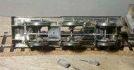
In this shot the Mitsumi motor is fitted in the adapted Multi-Box that was originally in my Black Motor. With this motor that was deemed a tad sluggish at 53:1, and I'm hoping for better things with a 40:1 gear set fitted in the box. The rear anchor point is at the trimming screw and allows side to side movement, and because the anchor is above the axle a small amount of fore and aft movement is also permitted. In fitting the gearbox the wheels have inadvertently been moved about and the heavy bind encountered earlier has returned. New and catching the light are the guard irons soldered to the inside of the frames replacing the 4F ones removed when I reprofiled the frames.

In their locating holes are the sandboxes with their oh so fragile white metal pipes. On the Beattie drawing there is quite a gap between the leading sandbox and the brake hanger bracket. On my model I had to hollow the sand box out as it slightly overlapped the bracket. Looking at photos of the prototype, it seems they probably abut. The fillers on the running plate do line up with the boxes so that's a win, but the white metal sand pipes will be replaced with phosphor bronze ones with some representation of the cocks - certainly for the front ones.
2022-06-30_20-19-15_687.jpg
Getting there... The rear tender step has clearly taken a knock in the process of me fitting the guard irons that are immediately behind them. It has to be said that the material used for the etch could have been a little thicker. The tender frames are hyper flimsy and a little too far apart for the guard irons attached to them to look much like the prototype even in EM. Next up I need to thin the centre axleboxes slightly to obtain adequate side play for the gearbox, and then I can fit the worm and gears, and provide some pickups. Once connected up, it will be interesting to see how well the beast moves with this motor and gearing.
 
Last edited:

Stevers

Western Thunderer
The return of the bind turned out to be significant. On closer examination, it turns out I had four wheels with weights fitted, but three of them were not insulated. The other three wheels (two without a weight) were insulated. This explained the strange arrangement of wheels on the Jidenco Black Motor that I had purchased to re-chassis to EM. As these are just build wheels it hardly matters, except for that bind, where the options for re-arranging the wheels were now limited. So I bit the bullet, Araldited some brass 10BA thread into the two affected wheels and re-drilled the crankpin holes using my jig. This time even though I used Araldite Rapid instead of Ultra and only waited hours rather than a day it worked, and the chassis rolled freely again with insulated wheels one side and uninsulated wheels the other.
P7070326.JPG
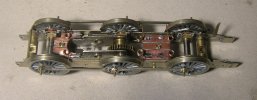
The chassis with its odd set of build wheels, showing the original style Multi-Box with the holes that I added to mount the Mitsumi motor (drawing below). On the two Mitsumi motors that have been in this gearbox, in neither case were the mounting holes quite equidistant from the shaft, so that they only meshed correctly one way round. The two motors were completely interchangable so must have been the same. Just visible are the cutouts in the sides to clear the large heads of the screws provided. Despite this, the motor ends up at a slight angle and therefore takes up more room than the nominal 12mm width.
Demounted are the demountable brakes. The front sandboxes are shown rebated to clear the front brake hanger bracket. The trim screw doubles as the rear motor anchor. Normally I'd run a solid wire from one of the motor terminals to a piece of PCB mounted on the chassis, but for a vertical motor this seemed a better option. I did contemplate fitting a flywheel in that capacious boxy firebox (at least in Black Motor terms), but I reckoned said flywheel could only be 4mm thick if that.

P7070327.JPG
The pickup pads screwed to the SEF cross-members with the PB pickups fitted. The pads are made of fibreglass copperclad which is very resistant to heat. The front one is straightforward, but the rear one has to clear the drive worm and is double thickness to set the pickups at the correct height. The gearbox needs to be able to move from side to side with the centre axle, and the gearbox frame needed some cutouts to clear the rear cross-member that had already been cut out for the worm drive. With the pickups fitted and adjusted to be lightly sprung - free running it is no longer - and there's just a trace of pickup squeal too. Someone had already ensured that there was room between the centre axleboxes for the gearbox, I guess that was me before that Wills T9 jumped the queue.
 

Attachments

  • Holes for Mitsumi motor.pdf
    45.3 KB · Views: 5

Stevers

Western Thunderer
In something of a surprise development, I decided that the parallel boiler had to go. After contemplating whether the SEF Q class boiler could be obtained and be the correct size or not, I found the perfect piece of 20mm brass tube in my stash. It was slit down the middle whereupon it sprung apart, and was then wrangled into more of a taper shape. Suitable sized formers were then soldered in just short of each end, and a triangular fillet soldered in to fill the gap. The most difficult part was filing the ends 'square' to give an even taper. The 4F boiler was cut off just shy of the boiler bands, and it was found that the taper boiler was a push fit into the 4F smokebox once I had scraped away the remains of the boiler inside the smokebox ring.
P7090333.JPG
There was a bit of collateral damage to the smokebox ring, but once the solvent is set I'll tidy that up. The taper is noticeable, and probably worth the effort, but not really the most useful thing I could be doing to the Q today. Of that poor old Airfix 4F body, just the much modified backhead and almost completely clad smokebox left! Looking at photos suggests that I need to do a bit more rounding of the firebox corners.
 
Top