JasonD
Western Thunderer
Just in case:
Jason
Jason

Mick,I've been bouncing around the Roco/Atlas chassis drive train for some years, it's not the best in the world but it works reasonably well, side frames look okay to me and they're cheap as chips.
The only problem is the rather high input drive line and transfer tower which inflict their ugliness into the cab. I did manage to flip the tower around and reduce the impact but it was still there and if driven the shaft still ran through the cab. To that end I decided to only power the rear truck and somehow cut down the front truck to clear the floor.
In a parallel universe I wasn't happy with the RC GP9 chassis being plastic so set about developing a new nickel silver etched version that fits the GP-9 and uses all the bits from said model and Roco/Atlas F9. I kn ow there are milled plates out there and many other options but I went for etched for several reasons, I'm in control, I own it and can tweak as I see fit, there are no import charges or 4-8 week delivery times. More importantly it'll be cheaper and have extras that milled frames et al do not have, aka full fishbelly under frame beams, webs, flanges, fabricated coupler pocket and pilot rear reinforcing plate work.
With that in mind the two universes crossed and as the moons aligned it was possible to make the new chassis fit a new style of un powered front truck. The new chassis should hopefully come late next week and I'll do a test build to see if it all fits.
Whilst that was all going on the new cut down front truck was tackled, several options were explored (mentally) and discarded, the problem here is hanging onto what Roco/Atlas and RC already have, the reality is that you've an open field and it takes a while for that penny to drop, well it did for me. The upshot is that rather than mess with the existing trucks I could just print new ones.
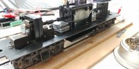
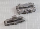
The Mk I truck is pretty much a clone of the Roco/Atlas truck with out most of the tower, it's shape and form follow pretty much the same shape, monkey see monkey do. To fit you simply cut the old tower bracket off, plate over the gap and using the centre screw secure the new truck.
View attachment 161463
On the new chassis that option is just a flat plate across the hole but that'll have to be a supplement (or on the Mk II if any revisions are required) as I only just thought of making the truck top level with the chassis top. The initial plan was to have the raised section a little higher but still below floor level. I still need to adjust the height of the fixing but it's close as it stands.
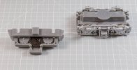
View attachment 161464
The raised section runs full length and matches the Roco truck, the disc is inserted after printing as it removes an overhang and distorted printing with supports that need cutting out. It occurred to me as I took the photos that I really didn't need the length of the the raised bit as there are no gears in there now, Mk II will have the whole raised block removed and the round disc extended down to the main larger block, that will daylight the view across the truck at low levels, possibly pointless as the rear will still be blocked. I may also add some detail to the block on the top to represent the transverse bolster where it joins the side frames above the main springs.
Removing the raised section and just leaving the round tower then means you can close off pretty much all of the bog bone opening in the chassis, you can either leave one big hole for the tower to rotate in, or slab the whole lot and just have a small hole for the fixing screw, that'll all fall under MK III experimentation if the below doesn't work out, I'm may still do it anyway as I'm still happy with one driven truck.
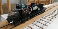
Moving onward and accepting you can pretty well make what you want it naturally came to the point of wondering if I could hack the design to get a below cab floor drive, well you can.....just.
View attachment 161465
The tower is reduced to the bare minimum and the top plate just fits below the floor, I say just as the 6BA fixing nut that holds the center peg will just impinge on the floor plate. At the moment the powered truck is very much work in progress so only the base core is done and being tweaked as I go along.
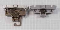
View attachment 161466
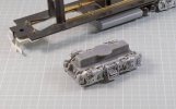
The trick here is to shuffle the gears around and find a decent orientation that holds as much of the shape square as possible, near impossible in SLA printers so it's just printed flat as it would be sat in the engine, that means there are ripples, artifacts and pooling to contend with. However, being as virtually none of this is visible it doesn't really matter (epiphany No 2) and can be printed at minimum to speed up the print times. Any imperfections can just be sanded or filed smooth as there are no surface details to worry about.
The problem here is that the three (32T) gear wheels from Roco won't fit the new arrangement so some math and trig resulted in the need for a new 25T gear, they came out well and work just fine, meshing with both the wheel and primary gear (black). I have a couple of split gears on axles so will work up a new gear there as well, the plan is to add a beefier shoulder each side of the actual gear to prevent them splitting again.
If they don't work then I'll just import some NWSL brass wheels and sets, i'd rather not and try to get better profiled wheels in the UK and modify them to fit with a bespoke gear.
To be honest the resin I'm using probably will not suffice long term or long running but as a proof of concept it's fine now and maybe for light use in a model. The alternative is a stronger more durable resin of which they are available from Form, so long as you buy a new tank (£144) and new resin cartridge (£144).
View attachment 161467
The upshot of the low line drive truck is moving the input shaft down by about 15 mm, more importantly, below the cab floor. Currently I'm tuning the fixings for the worm and bronze bearings so hopefully that all be done on the next print and I power up the whole drive train.
One down side to printing with no angle is that the truck exhibits a bit of a sag in the middle, the curse of large parts in SLA printers, in this instance no angles actually works better than angling the part as other areas then tend to sag or ward which cannot be overcome (easily).
Once I'm happy all the bits fit and work and the cover plate is signed off then the base unit will be redesigned with a inverse sag (hog) in the master, thus when printed it should come out pretty flat. To be honest, the warping makes no odds or has an effect on the running, it's just a visual thing and being as virtually none of it is visible when fully assembled it's more a niggle than a must resolve point.

I’m very glad I haven’t started mine yet!I've been bouncing around the Roco/Atlas chassis drive train for some years, it's not the best in the world but it works reasonably well, side frames look okay to me and they're cheap as chips.
The only problem is the rather high input drive line and transfer tower which inflict their ugliness into the cab. I did manage to flip the tower around and reduce the impact but it was still there and if driven the shaft still ran through the cab. To that end I decided to only power the rear truck and somehow cut down the front truck to clear the floor.
In a parallel universe I wasn't happy with the RC GP9 chassis being plastic so set about developing a new nickel silver etched version that fits the GP-9 and uses all the bits from said model and Roco/Atlas F9. I kn ow there are milled plates out there and many other options but I went for etched for several reasons, I'm in control, I own it and can tweak as I see fit, there are no import charges or 4-8 week delivery times. More importantly it'll be cheaper and have extras that milled frames et al do not have, aka full fishbelly under frame beams, webs, flanges, fabricated coupler pocket and pilot rear reinforcing plate work.
With that in mind the two universes crossed and as the moons aligned it was possible to make the new chassis fit a new style of un powered front truck. The new chassis should hopefully come late next week and I'll do a test build to see if it all fits.
Whilst that was all going on the new cut down front truck was tackled, several options were explored (mentally) and discarded, the problem here is hanging onto what Roco/Atlas and RC already have, the reality is that you've an open field and it takes a while for that penny to drop, well it did for me. The upshot is that rather than mess with the existing trucks I could just print new ones.
The Mk I truck is pretty much a clone of the Roco/Atlas truck with out most of the tower, it's shape and form follow pretty much the same shape, monkey see monkey do. To fit you simply cut the old tower bracket off, plate over the gap and using the centre screw secure the new truck.
View attachment 161463
On the new chassis that option is just a flat plate across the hole but that'll have to be a supplement (or on the Mk II if any revisions are required) as I only just thought of making the truck top level with the chassis top. The initial plan was to have the raised section a little higher but still below floor level. I still need to adjust the height of the fixing but it's close as it stands.
View attachment 161464
The raised section runs full length and matches the Roco truck, the disc is inserted after printing as it removes an overhang and distorted printing with supports that need cutting out. It occurred to me as I took the photos that I really didn't need the length of the the raised bit as there are no gears in there now, Mk II will have the whole raised block removed and the round disc extended down to the main larger block, that will daylight the view across the truck at low levels, possibly pointless as the rear will still be blocked. I may also add some detail to the block on the top to represent the transverse bolster where it joins the side frames above the main springs.
Removing the raised section and just leaving the round tower then means you can close off pretty much all of the bog bone opening in the chassis, you can either leave one big hole for the tower to rotate in, or slab the whole lot and just have a small hole for the fixing screw, that'll all fall under MK III experimentation if the below doesn't work out, I'm may still do it anyway as I'm still happy with one driven truck.
Moving onward and accepting you can pretty well make what you want it naturally came to the point of wondering if I could hack the design to get a below cab floor drive, well you can.....just.
View attachment 161465
The tower is reduced to the bare minimum and the top plate just fits below the floor, I say just as the 6BA fixing nut that holds the center peg will just impinge on the floor plate. At the moment the powered truck is very much work in progress so only the base core is done and being tweaked as I go along.
View attachment 161466
The trick here is to shuffle the gears around and find a decent orientation that holds as much of the shape square as possible, near impossible in SLA printers so it's just printed flat as it would be sat in the engine, that means there are ripples, artifacts and pooling to contend with. However, being as virtually none of this is visible it doesn't really matter (epiphany No 2) and can be printed at minimum to speed up the print times. Any imperfections can just be sanded or filed smooth as there are no surface details to worry about.
The problem here is that the three (32T) gear wheels from Roco won't fit the new arrangement so some math and trig resulted in the need for a new 25T gear, they came out well and work just fine, meshing with both the wheel and primary gear (black). I have a couple of split gears on axles so will work up a new gear there as well, the plan is to add a beefier shoulder each side of the actual gear to prevent them splitting again.
If they don't work then I'll just import some NWSL brass wheels and sets, i'd rather not and try to get better profiled wheels in the UK and modify them to fit with a bespoke gear.
To be honest the resin I'm using probably will not suffice long term or long running but as a proof of concept it's fine now and maybe for light use in a model. The alternative is a stronger more durable resin of which they are available from Form, so long as you buy a new tank (£144) and new resin cartridge (£144).
View attachment 161467
The upshot of the low line drive truck is moving the input shaft down by about 15 mm, more importantly, below the cab floor. Currently I'm tuning the fixings for the worm and bronze bearings so hopefully that all be done on the next print and I power up the whole drive train.
One down side to printing with no angle is that the truck exhibits a bit of a sag in the middle, the curse of large parts in SLA printers, in this instance no angles actually works better than angling the part as other areas then tend to sag or ward which cannot be overcome (easily).
Once I'm happy all the bits fit and work and the cover plate is signed off then the base unit will be redesigned with a inverse sag (hog) in the master, thus when printed it should come out pretty flat. To be honest, the warping makes no odds or has an effect on the running, it's just a visual thing and being as virtually none of it is visible when fully assembled it's more a niggle than a must resolve point.


I'd be interested to see how you gear the wheel to the unit, the RoW wheels have the gear in the middle of the axle, it may shift to one end but then the axle box might need to come in board.Des Planes came through with the fuel tank parts. Two pieces on one sprue arrived in the mail today. I also have some wheels from Right-O-Way meandering their way through the postal service. I have an idea for the drive. N20 gearmotors are too big, but I have some N10s on order. Should be able to hang them off the axles…

It does depend on what ratio you opt for and the motor shaft speed, I'm thinking something around 500 rpm will be mid range, you can always change the final ration with the gears on the output shaft and wheel axle. I've yet to work out what wheel rpm you'd need for GP-9 wheels at say 50 mph.I didn't buy wheels with gears. I bought 8 40" wheels with plain 1/8" axles. Actually I'm not sure if they have axles, but they take 1/8" axles. My idea is to 3D print a housing for the N10 that slips over the axle and then find gears to fit at the other end. I'll probably fit some top hat bearings left over from my P4 models onto the axle so that it doesn't wear the resin. There is a risk that it will end up being geared really low, but I won't know until I try. I'm not sure about cosmetics yet, but functionally this will be close to the prototype.
