Rob Pulham
Western Thunderer
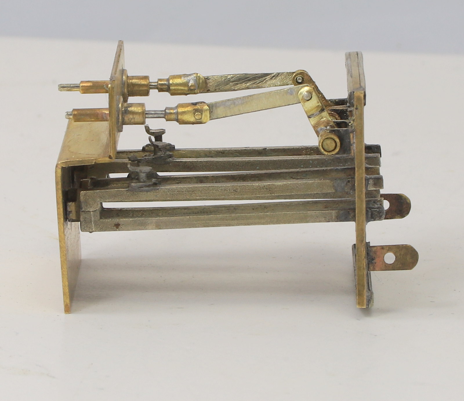
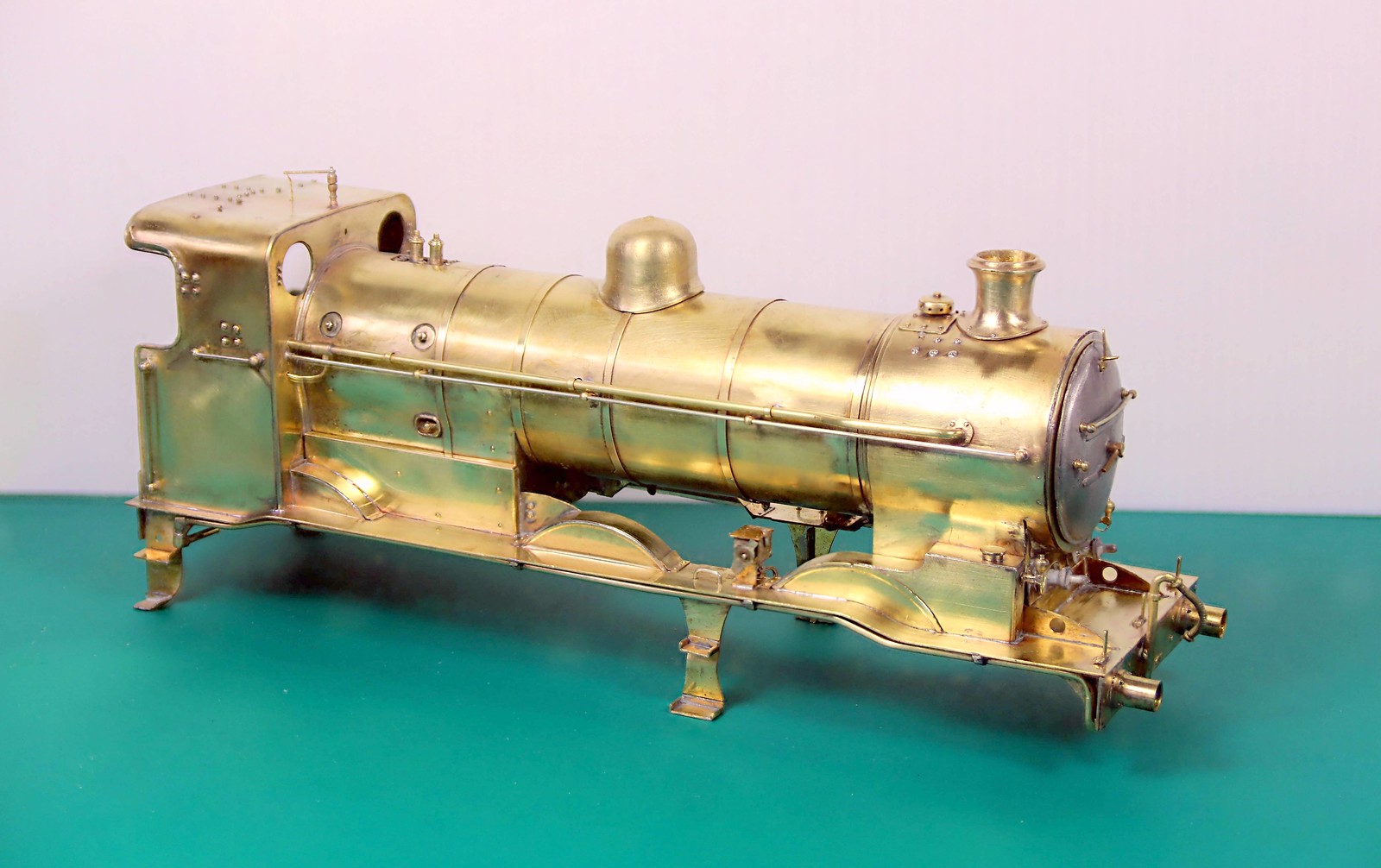
Modelling time this last week has seen me back on the J6. I have been making progress with the inside motion starting with soldering the front of the slide bars to the cylinder front and then removing the motion bracket and moving it backwards to match the drawing in order that it would then clear the front horn guides.
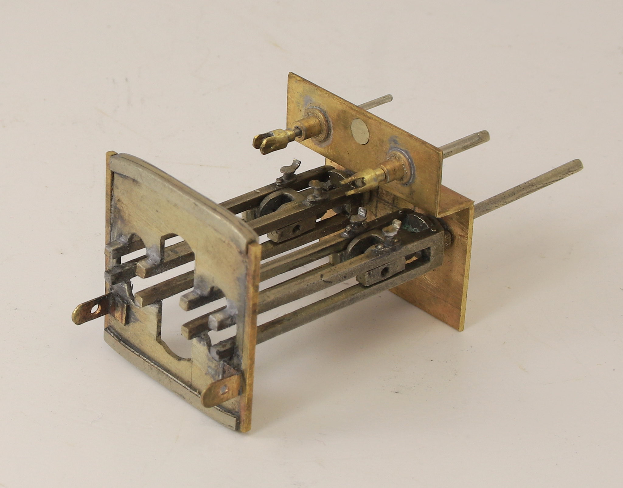
Getting them square to each other was a little challenging so I cut a couple of rectangles of 10thou sheet to set both the distance between the cylinder front and the rear of the motion bracket and keep them square at the same time. I used a couple of aluminium hair grips to hold them in place while I soldered the ends of the slide bars to the motion bracket.
I still need to plot out and drill holes for the support rods for the expansion links in the cylinder front.

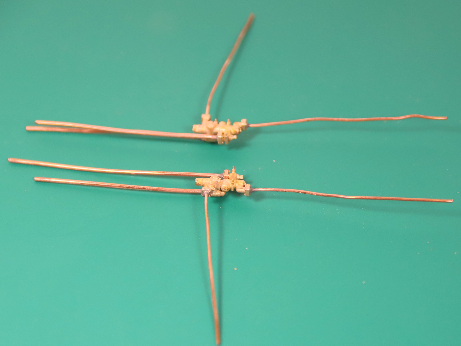
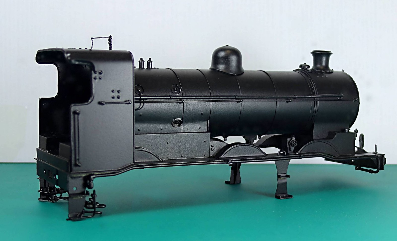
I have temporarily assembled most of the motion but I still need to add the parts to the motion bracket which support and operate the valves.


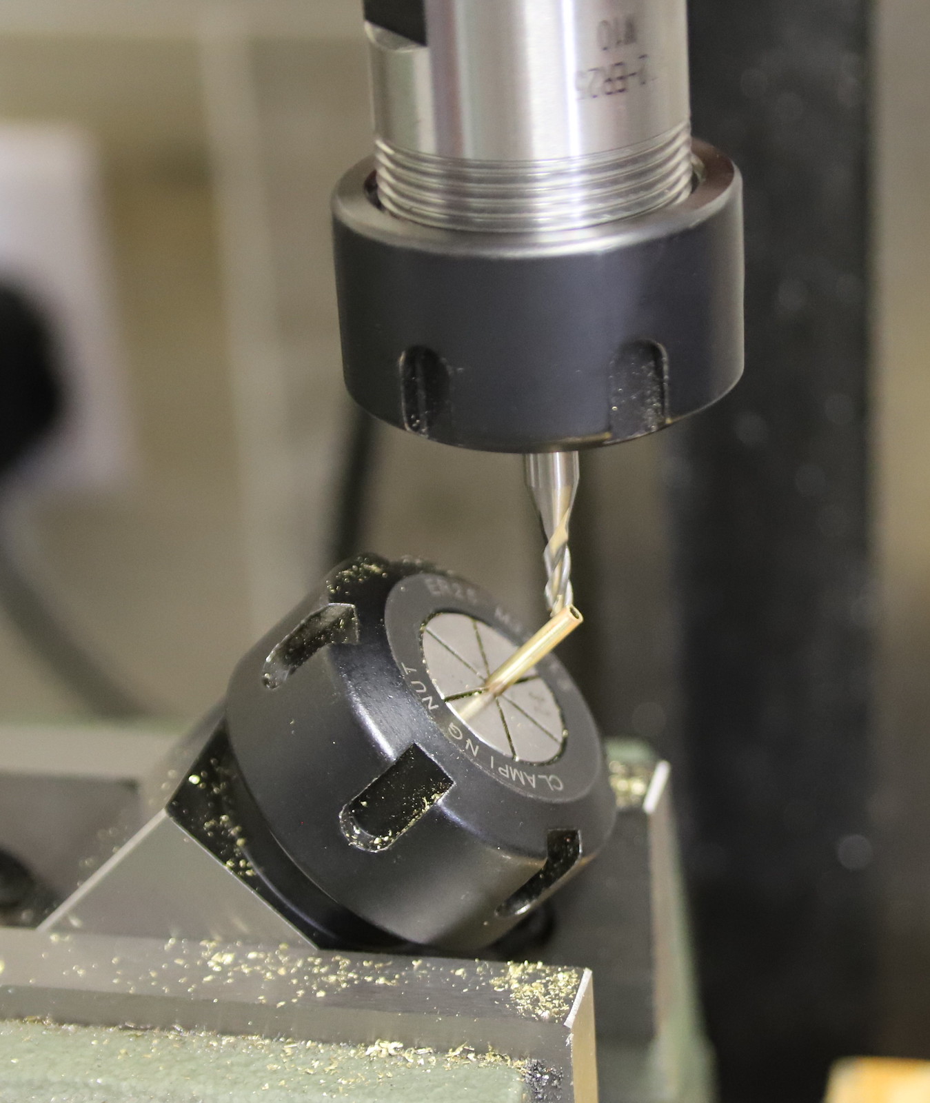
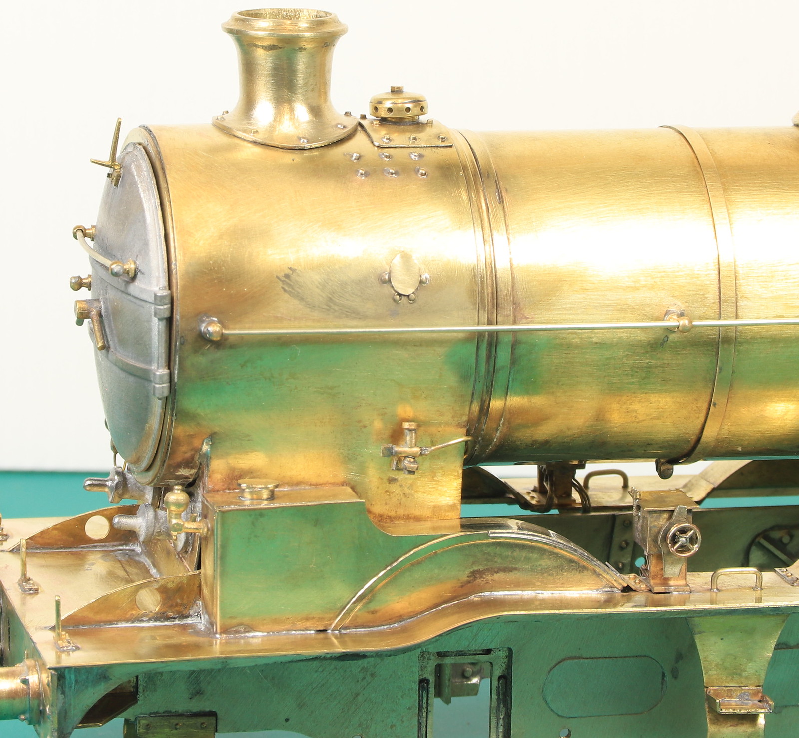
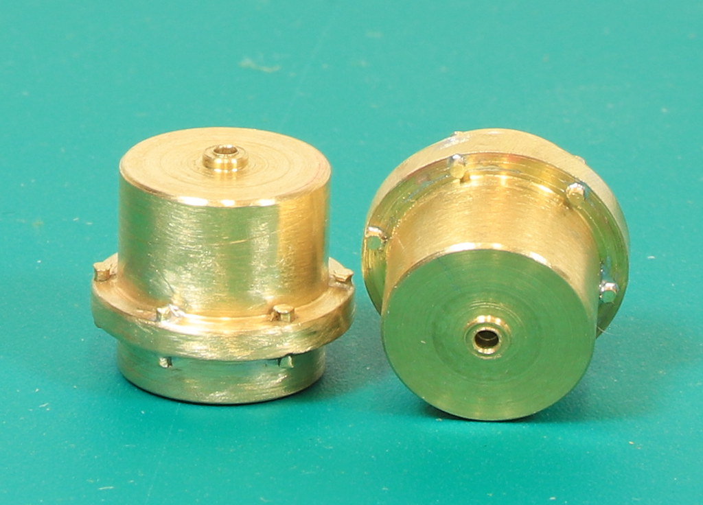
Having extended the clearance between the cylinder front and the motion bracket so that the cylinder front sits in front of the horn guides, I found that the slide bars still fouled the horn guides. T next task was to reduce the depth of the front horn block in the lathe so my four-jaw chuck got a turn. Because I only wanted to effectively face them off. I cheated a little and fitted a short length of 3/16” silver steel into the tailstock, slipped a bearing on and used that to quickly centre the four jaw.
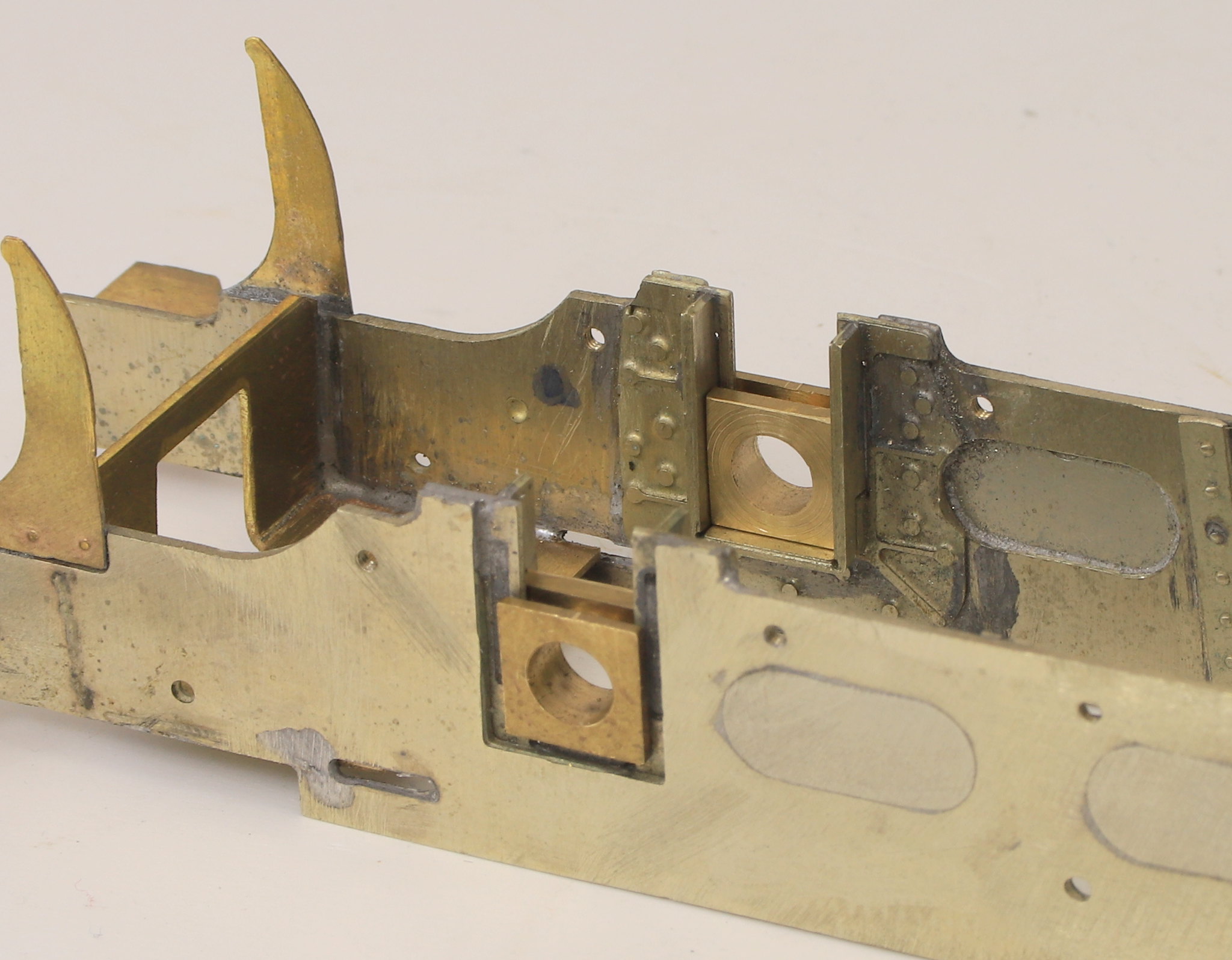
The next task is to remove a section of the horn guides to clear the slide bars.

As soon as funds allow, I plan to buy a mill to compliment the lathe and boy would a mill make this task easier. I can see now why Nick plans his inside motion fitting as he builds the frames. A lesson learned for the future! Onwards and upwards as they say.

Getting them square to each other was a little challenging so I cut a couple of rectangles of 10thou sheet to set both the distance between the cylinder front and the rear of the motion bracket and keep them square at the same time. I used a couple of aluminium hair grips to hold them in place while I soldered the ends of the slide bars to the motion bracket.
I still need to plot out and drill holes for the support rods for the expansion links in the cylinder front.

I have temporarily assembled most of the motion but I still need to add the parts to the motion bracket which support and operate the valves.


Having extended the clearance between the cylinder front and the motion bracket so that the cylinder front sits in front of the horn guides, I found that the slide bars still fouled the horn guides. T next task was to reduce the depth of the front horn block in the lathe so my four-jaw chuck got a turn. Because I only wanted to effectively face them off. I cheated a little and fitted a short length of 3/16” silver steel into the tailstock, slipped a bearing on and used that to quickly centre the four jaw.

The next task is to remove a section of the horn guides to clear the slide bars.

As soon as funds allow, I plan to buy a mill to compliment the lathe and boy would a mill make this task easier. I can see now why Nick plans his inside motion fitting as he builds the frames. A lesson learned for the future! Onwards and upwards as they say.


")