JimG
Western Thunderer
This all started about five years ago when I was Parts Officer for the S Scale Model Railway Society. There was a possibility of some Grouping era cast resin wagon bodies appearing on the Parts shelves and I had no solid spoked wheels to go with them due to difficulty in getting the wheels from our normal suppliers. So I opted to DIY using 3D printed centres, turned steel tyres and parallel journal axles. I was able to get tyres and axles from another of our suppliers and I had my own 3D printer. Things went quite well and I produced almost one hundred axles. But there was a fair bit of wastage since I tried to keep the TIR of the wheels to a maximum of 0.003" and anything outside this parameter was junked. (Well not completely junked since the 3D printed centre could be knocked out of the defective wheel, and the tyre re-used). I stood down as Parts Officer and my successor finally got a large supply of wheels with pin-point axles from one of our suppliers so my efforts are stored away for anyone wanting parallel journal axles - pin point axles are the SSMRS standard. My reasons for using parallel journal axles were twofold - the main one being that I couldn't get a small enough minimum order for pinpoints and the selfish one being that I wanted parallel journals for springing. ")
So move forward to last year and I had started work on my sprung S scale wagons again and I needed some wheels on axles, and I had a load of tyres and axles lying around. I also wanted to see if I could get a better success rate in getting the wheels running to 0.003" TIR or better. In the previous exercise I had printed the axle hole in the centres and finished it off with a reamer. So the problem could have been with this method and I wanted to investigate mounting the wheel centre, with no axle hole printed, and tyre in a collet on the lathe and drilling the axle hole. I had several goes at making split step collets in steel but couldn't achieve repeatable accuracy when using them. Then I saw @Giles 3D printed split collets and tried some myself and got excellent results with very low runout.

...but I ran into problems when I started putting it to fairly intensive use when the collet started to lose its accuracy. I tried beefing up my design but I suspect that the short 0 MT taper in the Cowells headstock was probably the main problem since it didn't allow much meat around the base of the collet jaws which was allowing them to flex a bit more that I had hoped.
So I started thinking about another wheel holder which didn't involve splitting it. and thought about building a form of magnetic chuck. First I would need a bit of non-ferrous metal of reasonable diameter. I had a dig around in the outside workshop and found a five inch bar of 1 1/2" diameter brass bar!!! I think this was purchased many years ago to use for centres for Scale 7 driving wheels.
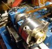
So I hacksawed about 20mm off the end and chucked it up in the Cowells, which the three jaw just about coped with. And backgear was needed as well.

...then took what would become the back of the holder down to 24mm diameter.
I then turned the piece around and took the front down to 28mm diameter.

You can see where most of the bar has gone. The piece has also gained a 6mm central hole, this to give, initially, a line up provision for the following CNC operation, and then later, a start for the internal boring operation
The piece was then set up on the CNC mill to machine the two holes for the magnets

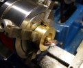
The piece then went back onto the lathe and the opening was bored to take the tyre.

The hole was bored until the holes for the magnets just appeared. The inner diameter of the bore cleared the tyre of the wheel. But this was opened out to just clear the flange for 1mm depth at the outer end so that the flange would sit against the small lip. You can just see this lip in the picture. The outer diameter for the holder was also skimmed at the same time to ensure it was concertric with the bore for the tyre - this to allow provision for checking accuracy in later setups.

A bit of thin sheet brass was set up in the CNC mill to machine a cover for the rear of the holder.

The magnets to be used were a couple of 4mm diameter x 8mm neodymium ones.

Here are all the bits before assembly.

The magnets are just showing in the holes.

The cover is screwed on the rear - and this is really necessary. If these magnets get within an inch or two of anything ferrous, they are off. I actually lost two during the process and found them stuck to the blade in the Junior hacksaw a while later. This also gives me a chance to use a couple of 12BA screws which I got in a packet of 100 from Whistons about fifty years ago. Members of a certain era may remember Whiston's catalogue.

A wheel is inserted in the holder and held by the magnets. There's minimum clearance to allow easy insertion and removal of the tyre, so maybe allowing not more than 0.001" TIR. There is sufficient friction to allow drilling and reaming of the axle hole even with leaving a small air gap between the tyre and the magnets. I think I would get a lot more friction (stiction?) if I let the tyre touch the magnets, but I think getting the tyre back out could be a major problem.
Jim.
So move forward to last year and I had started work on my sprung S scale wagons again and I needed some wheels on axles, and I had a load of tyres and axles lying around.
I also wanted to see if I could get a better success rate in getting the wheels running to 0.003" TIR or better. In the previous exercise I had printed the axle hole in the centres and finished it off with a reamer. So the problem could have been with this method and I wanted to investigate mounting the wheel centre, with no axle hole printed, and tyre in a collet on the lathe and drilling the axle hole. I had several goes at making split step collets in steel but couldn't achieve repeatable accuracy when using them. Then I saw @Giles 3D printed split collets and tried some myself and got excellent results with very low runout....but I ran into problems when I started putting it to fairly intensive use when the collet started to lose its accuracy. I tried beefing up my design but I suspect that the short 0 MT taper in the Cowells headstock was probably the main problem since it didn't allow much meat around the base of the collet jaws which was allowing them to flex a bit more that I had hoped.
So I started thinking about another wheel holder which didn't involve splitting it. and thought about building a form of magnetic chuck. First I would need a bit of non-ferrous metal of reasonable diameter. I had a dig around in the outside workshop and found a five inch bar of 1 1/2" diameter brass bar!!! I think this was purchased many years ago to use for centres for Scale 7 driving wheels.
So I hacksawed about 20mm off the end and chucked it up in the Cowells, which the three jaw just about coped with.
And backgear was needed as well. ...then took what would become the back of the holder down to 24mm diameter.
I then turned the piece around and took the front down to 28mm diameter.
You can see where most of the bar has gone.
The piece has also gained a 6mm central hole, this to give, initially, a line up provision for the following CNC operation, and then later, a start for the internal boring operationThe piece was then set up on the CNC mill to machine the two holes for the magnets
The piece then went back onto the lathe and the opening was bored to take the tyre.
The hole was bored until the holes for the magnets just appeared. The inner diameter of the bore cleared the tyre of the wheel. But this was opened out to just clear the flange for 1mm depth at the outer end so that the flange would sit against the small lip. You can just see this lip in the picture. The outer diameter for the holder was also skimmed at the same time to ensure it was concertric with the bore for the tyre - this to allow provision for checking accuracy in later setups.
A bit of thin sheet brass was set up in the CNC mill to machine a cover for the rear of the holder.
The magnets to be used were a couple of 4mm diameter x 8mm neodymium ones.
Here are all the bits before assembly.
The magnets are just showing in the holes.
The cover is screwed on the rear - and this is really necessary. If these magnets get within an inch or two of anything ferrous, they are off.
I actually lost two during the process and found them stuck to the blade in the Junior hacksaw a while later. This also gives me a chance to use a couple of 12BA screws which I got in a packet of 100 from Whistons about fifty years ago. Members of a certain era may remember Whiston's catalogue. A wheel is inserted in the holder and held by the magnets. There's minimum clearance to allow easy insertion and removal of the tyre, so maybe allowing not more than 0.001" TIR. There is sufficient friction to allow drilling and reaming of the axle hole even with leaving a small air gap between the tyre and the magnets. I think I would get a lot more friction (stiction?) if I let the tyre touch the magnets, but I think getting the tyre back out could be a major problem.
Jim.
Last edited: