Scratchbuilt machined gearboxes

Brian McKenzie

Western Thunderer
This solid one-piece brass gearbox was completed today (all manual work), replacing the side plates of a standard Slaters GB30R-3M, which provided the Canon motor and gears.
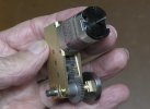
S3300004a 5th Brass Gearbox 50DP 30 to 1.jpg

It's for my current locomotive project, where more distance or height was needed between motor shaft and the powered axle.
By arranging the intermediate shafts to be in a straight line, another 5mm was gained over the curved routing of shafts in the Slaters arrangement.
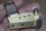
S3300012a 5th Brass Gearbox 50DP 30 to 1.jpg

I'm quite intrigued with the complexity of the Slaters gearbox, which I hadn't seen before. Busier than I would want to be making and assembling - but well done.
-Brian McK.
 

simond

Western Thunderer
Lovely bit of machining!

I’m perplexed by that, Brian. It’s probably the camera angle but I can’t see how the gear train works. I’m guessing the larger of the two gears on the middle intermediate shaft does not mesh with the smaller on the lower intermediate shaft, but that leads me to wonder how the gears (presume wormwheel, and pinion) on the upper shaft are arranged…. The clearance between wormwheel and the middle pinion must be minimal?
 

Brian McKenzie

Western Thunderer
Simon yes, there is very little clearance between gear teeth and the boss of the gear on the next shaft! From the motor shaft, a 9 tooth spiral gear meshes with a 15 tooth.

The 15 tooth is visible here. Photo shows the unfinished gearbox about to be first tested using an almost dead battery ex smoke alarm.

First test of unfinished gearbox.jpg
Arriving at and getting 90degree shaft spacing correct for spiral gears (and worm gears) is the only tricky part in cobbling up gear trains.

From measurements under high magnification, I judged this to be 0.268 inches. Without knowing what DP or Module these rather nice gears are, different formula values were tried, and it seems this pair of spiral gears are imperial 70DP - if indeed such terminology applies here.

The P.C.D. (Pitch Circle Diameter) of the

. . . . . . 9 tooth gear. . . . . . 0.07 (for 70DP). . x 9 (teeth) divided by π 3.1416 = 0.2005 inches

. . . . . 15 tooth gear. . . . . . 0.07 (for 70DP). . x15 (teeth). . . . " . . . . . . . . . " . . . = 0.3342

. . . . . . . . . . . . . . . . . . . . . . . . . . . . . . . . . . . . . . . . . . . . . . . . . . . . . . . . . . . . . . . . . . . . = 0.5347

. . . . . . . . . . . . . . . . . . . . . . . . . . . . . . . . . . . . . . . . . . . . . . . . . . . . . . Divide by 2 . . . = 0.26735 inches 0.268" had to be good!


However, this gearbox was easier than others made, as the motor position can be adjusted if necessary by sliding it along in the narrow recess which accommodates the plate that comes screwed to the motor.

-Brian McK.
 

Brian McKenzie

Western Thunderer
A clearer view of the gears. After the holes were drilled and reamed in the brass, the gears were placed externally on temporary shafts and given a spin to check all was well.

S3230019a Test fit and spin of gears.jpg


A 23x28 Maxon powered bronze gearbox for an earlier loco (still to be finished) with Module 0.5 gears all homemade. The housing can be split at the axle and the bottom section pulled off on the dowel pins.
It is whisper quiet with the Delrin gear. (Plastic gears are OK when they are cut from bar stock. It's moulded gears that can give grief.)

Edit: Module size should read 0.5, not 50 !!

S3300017a 4th Maxon bronze gearbox 50 module.jpg
 
Last edited:

michael mott

Western Thunderer
This solid one-piece brass gearbox was completed today (all manual work), replacing the side plates of a standard Slaters GB30R-3M, which provided the Canon motor and gears.

View attachment 227907

It's for my current locomotive project, where more distance or height was needed between motor shaft and the powered axle.
By arranging the intermediate shafts to be in a straight line, another 5mm was gained over the curved routing of shafts in the Slaters arrangement.

View attachment 227909

I'm quite intrigued with the complexity of the Slaters gearbox, which I hadn't seen before. Busier than I would want to be making and assembling - but well done.
-Brian McK.
I have to agree with Simon beautiful work.
Michael
 

paulc

Western Thunderer
It is indeed a thing of beauty and machined out of solid bar .
The two that I've made started with hollow brass square section then just machined one side out of it so i take my hat off to you Brian .
 

Brian McKenzie

Western Thunderer
The extended reach gearbox using the Slater's gear train was installed in this frame and uncompleted boiler (spoked wheels to follow).

The boiler is a lump of 3/4" stainless steel Schedule 40 pipe, conveniently measuring the required 1.050" dia O.D., - but coming with a 3mm wall thickness! The smokebox end turned nicely, but milling out the openings was something else. Not something I'll want to repeat.

S3430005a Motor gearbox fitted.jpg

Sandboxes on the running board, and leaf springs will help hide where the gearbox protrudes from the front of the firebox
- and below, with its saddle tank 'cover'.

S3430007a Saddle tank over motor.jpg

Brian McK.
 

Brian McKenzie

Western Thunderer
Please tell me the tank isn’t machined from solid too…

It's a fabrication, Simon - unlike previous tanks. :)

Casting about for a new project, I saw the saddle tank construction for Dave's Manning Wardle, and thought I'd like to try one like that.


It was the first item made, the shell pressed into a 'mould' hastily cobbled from bits of wood and quick setting car filler bog.

S2660003a Saddle tank bulkheads assembled on rods.jpg

The bulkheads were later hollowed out to suit the boiler diameter, when that had been determined.

S3340012a Internal bulkheads of saddle tank trimmed.jpg

Brian McK.
 

Brian McKenzie

Western Thunderer
Some more gearboxes:

S3330004a Gearbox using Sid Stubbs design features.jpg
This was made for a Sn3.5 project by following Sid Stubbs' excellent instruction in MRJ #42. The 2-start worm was spiral milled with a Unimat headstock resting on the cross-slide of a larger lathe - which had a separate bicycle chain drive temporarily added to rotate its spindle slowly at 6 rpm. Thrust ball races on the worm shaft use balls taken from ball-point pens.

I owe a lot to Sid, whose earlier MRN writings, during my school years greatly influenced the direction of my working life. About 1988, I was privileged to spend time with Sid and Mrs Stubbs at their Manchester home - and in amazing coincidence - learnt we had both experienced escapades in the vicinity of Khyber Pass, but during different decades!

S3330005a 2-start worm drive embedded in frame.jpg
Another 2-start gear drive to Stubbs' spec. integral to the underframe of an O gauge crane, from 35+ years ago. Silky smooth with thrust races.

-Brian McK.
 

Rob R

Western Thunderer
I have a couple of Sid's larger gearboxes stashed away for a rainy day and looking out of the window that day is not far off.
Sid was a wonderful chap, always helpful and supportive of the younger modeller, very much like Trevor Nunn.
Both are sorely missed.
Rob
 
Top