You are using an out of date browser. It may not display this or other websites correctly.
You should upgrade or use an alternative browser.
You should upgrade or use an alternative browser.
Simon's workbench
- Thread starter Simon
- Start date

Simon
Flying Squad
Slight change of tack, anticipating track laying outside, I last night "refurbished" one of the turnouts for the main junction, replacing a couple of lost chairs, refixing some loose ones and attaching a new "web" to hold everything together ahead of being fixed down. All of the soldered joints are good after so many years outside.


Simon
Flying Squad
On a bit of a roll, not too much mind, I have brought in from the garden the "grand daddy" point, which I fitted the tie bar to on the 9th May 2010 as shown here.

And here it is best part of twelve years later, all spent outside and having carried very many train movements.

The same drill, new web to be made to keep all timbers in place, a few chairs to be re-solvented to their timbers and I need to drill and solder the crossing V to the wing rails for strength and electrical guaranteed electrical continuity, which I didn't do on this very first point and which did give rise to a bent wire bodge..
The UV has "attacked" the S&C chairs, but that said they are all sound and glue back nicely. They look nicely weathered in fact!
I'm not quite sure what I think about the passage of time.....
Hopefully I will work on this tonight.
And here it is best part of twelve years later, all spent outside and having carried very many train movements.
The same drill, new web to be made to keep all timbers in place, a few chairs to be re-solvented to their timbers and I need to drill and solder the crossing V to the wing rails for strength and electrical guaranteed electrical continuity, which I didn't do on this very first point and which did give rise to a bent wire bodge..
The UV has "attacked" the S&C chairs, but that said they are all sound and glue back nicely. They look nicely weathered in fact!
I'm not quite sure what I think about the passage of time.....
Hopefully I will work on this tonight.

Overseer
Western Thunderer
Now you have sorted the turnouts out you can get on with developing your concept of time and its passing. Sounds like a good nocturnal activity.I'm not quite sure what I think about the passage of time.....
Hopefully I will work on this tonight.
Simon
Flying Squad
In a fit of something approaching enthusiasm I have tonight been down the shed and have mostly finished the point I was "working at" on my Railwells demonstration.

The remaining major task is the tiebar, which is always a major ball ache as it has to be mechanically robust but also insulated across its centre, I shall be replicating the tubular arrangement of the point I built last year (pictured) as these are sharp radius points situated off running lines in my imaginary world,
This point is the one that connects the "light railway" to the quay line on my garden scheme.
I am slightly narked as the flangeways on either side of the crossing nose are not exactly the same, bending and twisting code 180 stainless steel rail is quite a palaver, but it all works and is within the limits of acceptability I think...
Richard Gawler
Western Thunderer
Code 180 stainless must be really hard work.
When I built some 16.5 mm gauge points using FB rail, I cut a groove through the foot of the rail. I know it's not prototypical but it did mean the bends ended up where I expected them to be. The cut on the inside closes up and you can't see it, so there is only the opened-out cut on the outside to either live with or disguise.
When I built some 16.5 mm gauge points using FB rail, I cut a groove through the foot of the rail. I know it's not prototypical but it did mean the bends ended up where I expected them to be. The cut on the inside closes up and you can't see it, so there is only the opened-out cut on the outside to either live with or disguise.
Simon
Flying Squad
More work on the point(s) today, the new one is now complete bar the spacer blocks between switch rails and stock rails on the slide chairs, which I forgot about(!)
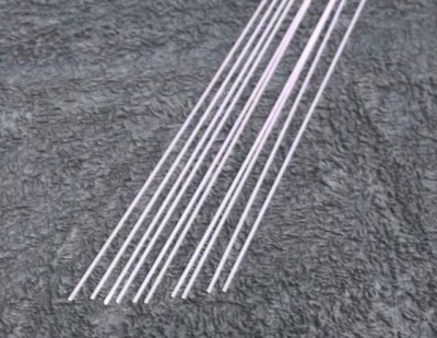
I earlier mentioned tiebars, here is my wheeze for a simpler tiebar (yes, I know its not called a tiebar in the real world).
Brass wire bent up, filed to suit switch rail which has had its foot filed away to accept end of brass wire, part soldered in to brass tube, both sides done:

Piece of styrene drilled through and filed to resemble tube, this forms a central insulator. The two halves are then joined by supergluing multicore wire which goes up inside the brass tube on both sides. Pictured here before gluing.

The drive rod will be soldered to one of the pieces of brass rod. This is quite a good solution as there is a bit of "flex" in the tiebar structure which eases operation.
Next is strengthening and electrically bonding the crossing and wing rail assembly, first of drilling in to the rail, for which a sharp drill is handy as the stainless isn't very soft.

Next I drill out some scrap metal strip and having soldered brass wire into the holes drop the strip over the resulting pegs and solder together. This picture is actually the earlier point, I did the same job to that one the afternoon after completing the "new" one.

Next the switch rails have to be electrically bonded to the stock rails.

So I now have two useable points for the "quay line". I am feeling moderately virtuous in the having "got off my harris and done something" department...

Maybe more progress tomorrow....
I earlier mentioned tiebars, here is my wheeze for a simpler tiebar (yes, I know its not called a tiebar in the real world).
Brass wire bent up, filed to suit switch rail which has had its foot filed away to accept end of brass wire, part soldered in to brass tube, both sides done:
Piece of styrene drilled through and filed to resemble tube, this forms a central insulator. The two halves are then joined by supergluing multicore wire which goes up inside the brass tube on both sides. Pictured here before gluing.
The drive rod will be soldered to one of the pieces of brass rod. This is quite a good solution as there is a bit of "flex" in the tiebar structure which eases operation.
Next is strengthening and electrically bonding the crossing and wing rail assembly, first of drilling in to the rail, for which a sharp drill is handy as the stainless isn't very soft.
Next I drill out some scrap metal strip and having soldered brass wire into the holes drop the strip over the resulting pegs and solder together. This picture is actually the earlier point, I did the same job to that one the afternoon after completing the "new" one.
Next the switch rails have to be electrically bonded to the stock rails.
So I now have two useable points for the "quay line". I am feeling moderately virtuous in the having "got off my harris and done something" department...
Maybe more progress tomorrow....
paulc
Western Thunderer
Hi Simon , i do like your soloution to tie bars but something i can't get my head around is where you say that the is an insulating peg to join the two halves (good) and then you superglue some multicore wire across . Doesn't this then create a path from one rail to the other and give you a short ?
I realise I'm probably being thick as obviously it doesn't but can you explain why not . Is the superglue acting as an insulator or do you leave the insulation on the wire ????
I realise I'm probably being thick as obviously it doesn't but can you explain why not . Is the superglue acting as an insulator or do you leave the insulation on the wire ????
paulc
Western Thunderer
Hi Simon , you don't think the insulating spacer in the centre if glued ( epoxy or super ) would hold up ?Sorry, that wasn’t well explained but you have got it, the multi core wire is completely sheathed, I just figured that this was effectively an insulating rod that would survive being put into tension. So far so good….
I ask as I'm thinking of upgrading my tiebars and this looks like a soloution that i could make .
simond
Western Thunderer
If looking for insulated rod, pultruded fibreglass is available in several diameters - I used some for insulated axles per Steph Dale’s method. It’s apparently used by anglers, and is easily available via eBay - otherwise it is supplied in long lengths by the manufacturers. I’d imagine it’s ideal for point stretchers.
e.g.
beware carbon fibre equivalents, they may well be conductive!
e.g.
Natural Fibre Glass Stems 48 @ 300mm Long 0.8mm / 1.0mm For Pole Float Making | eBay
Natural Fibre Glass Stem Material for float making. This is 30cm. long (a shade under a foot). 0.8mm & 1.0mm available. Listed in multiples of 48.
www.ebay.co.uk
beware carbon fibre equivalents, they may well be conductive!
Brian T
Western Thunderer
Hi Simon,In a fit of something approaching enthusiasm I have tonight been down the shed and have mostly finished the point I was "working at" on my Railwells demonstration.
View attachment 168874
This point is the one that connects the "light railway" to the quay line on my garden scheme.
Are these points REA #5's as i'm planning on using them on my small layout plus a three way too!.
Cheers,
Brian.
Simon
Flying Squad
Well that was all a complete waste of time as I couldn't get a drive rod attached to the tiebar, for various reasons. I think the suggestion of glass fibre rod is a good one, which would possibly have overcome the problem, but I decided it would be best to build one of my "tried and tested" tiebars.
I knew it would be a lot of work, and it was. I have just come in from the shed and reckon the whole thing has taken me about 5 hours one way and another. The next one should be quicker(?)
Cutting out brass ears, desired shape to left (a reject from the last time)

The second one work hardened and broke, owing to unsymmetrical bending on my part, so I had to make a third.
And attach them to half tiebars, bent in middle with more holes for bolts.

The middle bolts have to be insulated on one side, so I waist them below the heads and superglue cotton wound around the waisted section to provide insulation. I used steel bolts for this rather than brass as in the past, as it has more strength, which made filing off the threads harder work but is probably a better job.

Eventually after much trial and tribulation the job is completed.

I cut the over centre mechanism off another point as it is on the wrong side for its new location, I have another which includes a lever which I might do the same to and try re-using on this point, or possibly easier to build a new one
Time to sleep!
I knew it would be a lot of work, and it was. I have just come in from the shed and reckon the whole thing has taken me about 5 hours one way and another. The next one should be quicker(?)
Cutting out brass ears, desired shape to left (a reject from the last time)
The second one work hardened and broke, owing to unsymmetrical bending on my part, so I had to make a third.
And attach them to half tiebars, bent in middle with more holes for bolts.
The middle bolts have to be insulated on one side, so I waist them below the heads and superglue cotton wound around the waisted section to provide insulation. I used steel bolts for this rather than brass as in the past, as it has more strength, which made filing off the threads harder work but is probably a better job.
Eventually after much trial and tribulation the job is completed.
I cut the over centre mechanism off another point as it is on the wrong side for its new location, I have another which includes a lever which I might do the same to and try re-using on this point, or possibly easier to build a new one
Time to sleep!
Simon
Flying Squad
I set to this evening, and by cannibalising the B8 point and its lever that I made almost exactly six years ago have got the new point completely finished. Here is the B8 six years ago:

And here it is now, attached to the new point - and it works!!


And here is the original B8 point without its point lever, still useable but it doesn't fit in to the new scheme of things.

Feeling quite encouraged, best get on with the next one....
And here it is now, attached to the new point - and it works!!
And here is the original B8 point without its point lever, still useable but it doesn't fit in to the new scheme of things.
Feeling quite encouraged, best get on with the next one....
Simon
Flying Squad
Well it isn't very elegant or neat, but I have managed to graft the over centre mechanism on to the other new point, but using the existing "tubular" tie bar rather than building a new bolted one as previously.


I think it is sufficiently robust to use, the next thing is to fabricate the lever and pivot over the spring box so that it has a point lever too.
Off to Scalefourum this weekend so that's it on the railway for a bit....
I think it is sufficiently robust to use, the next thing is to fabricate the lever and pivot over the spring box so that it has a point lever too.
Off to Scalefourum this weekend so that's it on the railway for a bit....
Simon
Flying Squad
I have managed post Scaleforum (which was very good) to fabricate and fit the tinwork that will support a point lever, which will hopefully enable the point to be changed. All I need to do now is cut out a point lever and make a pivot pin….

But for some strange reason I feel moderately compelled to make a replacement windscreen wiper for D6319…..
But for some strange reason I feel moderately compelled to make a replacement windscreen wiper for D6319…..