Solid Edge - Community Edition

Ian_T

Western Thunderer
(Having posted recently about SE on anther thread – I thought it might be helpful to start a new thread just about SE to make it easier to find (and to stop hi-jacking other folks threads). So here goes:

What is Solid Edge?

Solid Edge is a 2D/3D (hybrid) parametric CAD system, offering ‘Ordered’ (history based) and ‘Synchronous’ modelling technologies. It runs on Microsoft Windows and provides solid modelling, assembly modelling and 2D orthographic view functionality for mechanical designers.

What is Solid Edge Community Edition?

The 'Community Edition' is essentially the same as the commercial SE version with two exceptions. The first is that native SE files created with SE-CE cannot be opened with a commercially licensed SE version (and presumably vice versa). The second is that ‘Draft’ drawings have a ‘SE-CE’ watermark on them. Otherwise all the SE basic functionality that normally costs over £2k pa (per seat) is provided by the Community Edition under a free lifetime license.

Where can I get Solid Edge Community Edition

This seems to have caused others some problems because there are various free, old and trial versions of Solid Edge still available on various Siemens pages/websites. So just 'Googling' can lead you astray. I would therefore strongly recommend that users should download from this Siemens link. It is a large download (about 6Gb) but it is a completely self contained software CAD package and made no real dent on my PCs 900Gb+ storage :

Siemens Digital Industries Software Online Store

As an aside, I downloaded SE-CE version ‘2020’ (which I am still using) last year but another ME I’ve been in contact with recently used this link and says his version appears to be the ‘2021’ Edition (with all the updates recently announced by Siemens for the commercial 2021 product). So this was very encouraging news!

What can Solid Edge NOT do?

SE will not suit you if you wish to run on Mac or Linux. It is Windows only and can be closely linked to external data via Microsoft technology (if you are clever enough). I run it on a five year old i5 laptop under Win 10 Home and have had no performance issues thus far.

It does not have a CAM component, so is not a one-shop stop for CNC. You can however export 3D designs for import into CAM software (including Fusion & FreeCAD) - so this may not be a limitation in practice. For 3D Print users it has an integrated 3DP slicer, although I'm still using Cura at the moment and haven't explored SE Slicer's 3DP features.

What can Solid Edge do?

Well just about everything else ’CAD’ as far as I can tell (although I’m no expert). My other ME/SE user correspondent was previously a professional ‘Solid Works’ user and he is of the view that he can do everything with SE that he could do with SW. That sounds like it’s going to be more than sufficient for my needs.

I should also add that I have been a TurboCAD 2D user for over 20 years and it is taking a little 're-thinking' of my approach to drafting. It’s not quite as simple as just "going from 2D drawing to 3D drawing" – you need to understand constraints, relationships, synchronous versus ordered design etc. However, it is possible to use SE-CE in 2D mode by using SE ‘Draft’ documents – and this 2D capability might be a much easier way to get into SE than just jumping into full 3D design. The 2D 'sketching' tools are essentially the same as used in 3D, so only need be learned once.

Why isn’t Solid Edge more widely known/used?

Siemens were a bit slow in offering a full 3D product for free (only starting in early 2020) although they had a free 2D product and various ‘Trial’ products before then. Some 3D CAD products, like Fusion 360 and Alibre had their offers earlier and therefore established a large (hobbyist) user base much earlier too. Also FreeCAD is developing/improving quickly as the open source solution - although I do not think it is up to 'commercial' quality software yet. I tried Fusion but didn’t progress with it, partly because I didn’t like the Cloud element. SE-CE is exactly right for my needs. It’s totally installed on my PC (locally) and I keep my work stored locally too, so there are no 'cloud' dependencies on future Corporate policy changes.

If anyone is interested, I will follow this up with some advice on how to get started with Solid Edge (from my own experiences as a 3D CAD Noobie). Siemens has provided some excellent eLearning and product documentation but it does sometimes takes some finding.

I hope this has been useful to anyone still wondering which CAD product might best suit their modelling needs going forward. Happy to answer questions if I can - please remember I'm still learning myself.

Regards,


IanT
 

Ian_T

Western Thunderer
I posted the above on another Forum and was asked there about "getting going" and posted this reply. It's just occured to me that some here might alsobe interested - so at the cost of a bit of cut 'n paste - here it is (in two parts)

OK, so you are new to 3D CAD and you have just downloaded Solid Edge Community Edition.

What to do next? Well I would suggest that one thing you DO NOT do – is just jump straight in and try to figure it out by yourself. It’s much better to be guided in your first few steps and I’d suggest the following ones..

Step 1
Open Solid Edge and click on the top menu option ‘Learn’ – this will take you to the ‘Learn Solid Edge’ page, where you should select ‘Recommended Learning Paths’ link.

This will then take you to an area of the Siemens’ ‘Doc Centre’ and I would suggest you choose the ‘New to CAD’ option (which I did even though I have some 2D CAD experience). Select ‘Click to Continue’

You will be offered three short intro videos – less than 20 minutes to watch them all.

Following the videos (on the same page) there are five eLearning Tutorials, each featuring a number of self-paced guided activities. An excellent feature of these activities is that although the learning material is online – you use the actual Solid Edge CAD package to work through them. So as you follow/work through each activity, you are building real 3D models using Solid Edge.

I worked through all five tutorials over about a week or so. At the end of this period, I was not a Solid Edge Guru but I had achieved one important thing. I knew that given time, I could draw reasonably complex objects in Solid Edge – because I had just done so. I believe that confidence is the first and most important thing that you need to learn when first coming to 3D CAD – and these Tutorials will help give it to you.

(BTW – there are many more Tutorials available should you need them...)

Step 2
Try to draw something relevant and useful to you, keeping it fairly simple to begin with. Try to stay within the bounds of the Tutorial work too. Don’t be too ambitious and don’t be afraid to scrap a drawing and start over if required.

The default setting for Solid edge is ‘Synchronous’ (although you can set ‘Ordered’ as your default if you wish). However, a key strength of Solid Edge is its Synchronous technology and it’s worth learning and using it.

End of Part 1
 
Last edited:

Ian_T

Western Thunderer
Part Two

Step 3
I watched many YouTube videos, some good and some frankly very bad. Some were also badly dated and/or used ‘Ordered’ methodology. Personally, I found that I learnt very little from videos that whizzed through the subject matter or were far too advanced.

Finally I settled on the YTs of Dr Mohammed Seif who is a University Lecturer in Engineering in the US. I suspect he originally made his videos for his students and they are well and (for my needs) well paced. His material is also sensibly structured and builds gradually, introducing new concepts in a reasonably logical way. I’ve now watched all of his material and sometimes pop back to check how he approached a particular part. Here is the first one...

Introduction to Solid Edge 2020 - Sketches (Introduction Lab) - YouTube

Step 4
As you progress with Solid Edge, you will discover ‘holes’ in your knowledge. There are several important aids to help get you past these roadblocks.

The first is with the Solid Edge user interface (UI) and is called the ‘Command Finder’. This is the box on the bottom of the screen that has ‘Find a Command’ in it! Type in a word that describes what you want to do and the Command Finder will open a box with the Commands you may be seeking. As you run your cursor over the suggestions, it will animate the associated icon in the Command Line to show you where it is located. A simple but very effective aid.

Secondly, assuming that you can find the Command you need but do not know how to use it, hovering over its icon and hitting F1 will take you to the ‘Help’ for that command – often an animated illustration.

Finally, Siemens has provided a set of very detailed ‘self-paced’ learning that can be downloaded as PDFs and which make a very good reference library. I have not worked systematically through them but have dipped into them as required. There are twelve ‘Fundamentals’ courses which cover more than most people will require I suspect. The ‘Sketching’ course downloads as a 216 page indexed document (and there is also an associated Powerpoint if required). I will probably never work through all this material but I do have the PDFs as a form of very detailed Reference Manual!

You can find the Self-Paced Courses here:

Siemens Documentation: Self-paced and classroom courses

So, that’s what I’d suggest to the ‘Younger Me’ if I’d had the chance a year ago. My progress wasn’t quite so orderly but I am happy to say I’m over the initial “That’s too hard to Learn” mentality. Like anything worth doing, you have to invest some time and effort.

Solid Edge is a very well documented and supported CAD product. I can’t make any comparisons with other CAD products but it’s certainly been a very important part of my learning thus far.

Hope this helps - sorry if it was a bit longwinded!
emsmile.gif


Regards,

IanT
 

Ian_T

Western Thunderer
And finally, there were some questions about using SE-CE just in 2D....

I mentioned in my initial post that Solid Edge CE could be used simply as a 2D CAD system and that this might be a good entry point for some people looking for small, gentle steps into 3D CAD.

Indeed, I've found myself prefering to use Solid Edge for my 2D work these days instead of TurboCAD but I've been aware that I still tend to approach 2D as I've always done with TC - and thereby not always getting the full advantage that a 2D parametric system can offer.

I found this YouTube recently and although it shows an older version of SE, there were a number of things that I hadn't realised were possible and that are proving useful in my 2D work. The ability to turn on projection lines is useful but being able to 'connect' items via them even more so - plus the ability to 'smartselect' elements by feature combinations (layer, colour etc) is very useful when managing layers.

These features are there, right in front of you but not always obvious to the novitiate I'm afraid. Anyway, for anyone using SE Community in 2D mode (or anyone who just wants a SE 2D preview) - this will be 17 minutes well spent.

Solid Edge - 2D Overview

Hope someone here finds this useful...if not please ignore! :)

Regards,

IanT
 

Pencarrow

Western Thunderer
Very interesting Ian, thanks. I do have a 3d printer sitting in a box in the trainroom and my intention when buying it was to produce lots of architectural bits for my 7mm buildings. Thoughts were along the lines of sash windows, tarty doors, chimney pots, valances etc but, seeing what others are doing, I suspect I've aimed too low.

Why is it still in the box? Heavily put off by all the lengthy threads on software requirements for drawing, rendering and slicing. I last used a CAD package over 20 years ago (autocad) and was totally lost on some of the suggested options.

Your post is encouraging me to download the software and have a go, although I have absolutely no idea what the following means:

"Solid Edge is a 2D/3D (hybrid) parametric CAD system, offering ‘Ordered’ (history based) and ‘Synchronous’ modelling technologies. ":confused:
 

Ian_T

Western Thunderer
In simpler terms Chris - you can use it to draw both 2D and 3D models.

Parametric - changes made in one part are reflected across all other assemblies (that use that part) and any drawings are also automically updated (which I find very convenient after using {non-parametric} TurboCAD for so long).

Many 3D CAD systems keep a step-by-step history (Ordered) of how you 'build' a part and you sometimes need to step back to the point where you want to change something (for mistakes & re-designs) and then redo the work from that point over again. 'Synchronous' tech let's you just change the part (e.g. no step back). Both methods have their uses & advantages but generally 'Synchronous' is the way to go for most design work and will save you time and assist productivity.

For a long time I felt 3D Print was a bit of a gimmick but was eventually tempted to buy a Solvol SV01. I have found it to be very useful for some aspects of my work. However, you really do need to be able to 'design' your own prints to get the best value out of one. A Gauge '3' friend suggested Open SCAD, which is pretty easy to get into but I quickly realised that SCAD wasn't going to solve all my 3DP needs (and none of my 2D drawing requirements) - or at least I wasn't going to be able to make it do so. :-(

Solid Edge CE is now pretty much my one stop CAD/Design shop and I'm really delighted with it. Still lots to learn but I feel I'm over the 3D 'hump' so to speak and it's certainly been fun learning and a good use of my time. Once you start 3D printing, you will find lots of uses for it but you obviously need to be able to design the things you want to print first! I'll attach a view of a custom PCB (DC motor controller) enclosure I designed in SE and printed on the SV01.

Good Luck!

Regards,

IanT

DC_Motor_Control_Box_3F.jpg
 

Attachments

  • DC_Motor_Control_Box_3F.jpg
    DC_Motor_Control_Box_3F.jpg
    43.4 KB · Views: 2

JimG

Western Thunderer
Ian,

I'm following your experiences - a bit like mine over the past month r so but I suspect that you might have been a bit more fastidious in following the tutorials. :) I had spent a year or two using Fusion 360 to generate work for my 3D printer so I have also had to get Fusion methods and vocabulary out of my mind and get with the Solid Edge way. :)

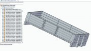
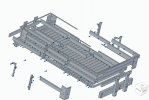
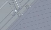
Today I've ventured into assembly after a day or two generating some .par files to use and after a few ups and downs, got under the skin and got a reasonable result.

SolidEdgePic-01.jpg

Apart from finding my way round Solid Edge I'm having to do a fair bit of pauchlin (Anglice - "fiddling" :)) ). The 16T mineral is made almost exclusively from 1/4" sheet steel which scales out at 0.1mm in S scale. I know that an 0.1mm side will not print in resin so there have been one or two tests with thicker sides (Body-01.par and Body-02.par in the files list) and I have had to go up to 0.6mm thickness to get a side which will be useable with the grey resin I am using.
Jim.
 
Last edited:

Ian_T

Western Thunderer
That's looking very good Jim.

There are limits on what you can scale of course and even in G3 a 1/4" panel would only be 0.28mm thick. Wooden bodies are a bit easier in G3, a 2.5" thick plank is 2.8mm thick (and 1 mm in 'S' I'd assume) and 3mm model aircraft quality 5-ply does this very nicely, so I've not been tempted to print them just yet. Never say never though! :)

Regards,

IanT
 

JimG

Western Thunderer
I've been using SE Community quite a lot over the past few months making files, for the mineral wagon I featured earlier. I'm getting on fairly well but it can get quite frustrating at times. :) I started off doing my wagon body in "Ordered" which allowed me to work in a similar way to how I had used Fusion 360 - basically, going back to the original sketches to alter them to adjust dimensions until I got a body side that worked. But as I delved further into the software I found that getting information on using the finer points of "Ordered" was quite difficult. I get the feeling that Siemens are keen for people to use the "Synchronous" method and provide copious amounts of help or documentation to support this, but virtually nothing for "Ordered". So I've been"forced" to use "Synchronous" for a lot of bits I'm doing purely because I can find information about the operations I want to do.

Another problem is actually finding information whether it's "Ordered" or "Synchronous". When I was assembling the body of the mineral wagon, I was getting on quite well with the major parts, but hit a problem when adding rivets. The rivets are comparatively small and when aligning them in assembly they could very often disappear into larger parts. I started digging around to see if there was a solution, and found one assembly tutorial which stated that you could place a component in a separate overlapping window when aligning it to the base part to avoid losing it. Unfortunately the tutorial didn't say how you could achieve two overlapping windows to do the placing operation. I spent a day searching the Internet to find out how to do this and finished up just bashing around the software trying to find the way to do it, but with no luck. I got round placing the rivets by finding the way to place them next to the base body so that they didn't disappear into another body, but it took a bit of time, with a fair few re-starts when I didn't choose a good place. :) Has anyone else found out how to do this overlapping window method? You set up the separate window placing in the Options, but that window is full screen and covers the main assembly window. Trying to move between the two windows to place the part finishes up after one change from separate window to main window, when the separate window disappears and the placing operation finishes.

Jim.
 

JimG

Western Thunderer
Still ploughing on with Solid Edge - CE and my latest model is a Caledonian Diag 24 four plank open. I thought about how I was going to build this in the software since I wanted the facility to put very small chamfers on the edges of planks to indicate plank joints. I've found out before that I sometimes have to experiment to get the best size of chamfer to produce a thin line which denotes the joint between planks. I know that in actual practice there are rarely any chamfers at joins, but if you model reality, the finished result ends up smooth off the printer. :) When I was using Fusion 360 I could set the chamfer size using a variable which could be altered very easily to produce a new outcome on all the chamfers, but I haven't delved deep enough into Solid Edge to see if I can do something similar.

I was also wanting to look more at the Synchronous method in SE - I've been tending to favour the Ordered method since it was a bit similar to working in Fusion with parametric control.

So I opted to work in Synchronous mode only, and to build the model using individual parts in the Assembly mode - i.e. build the wagon plank by plank. :) Here's the final result :-

Diag24OpenFinal.jpg

...and here's the exploded view...

Diag24Open-Explode.jpg


Not quite fully exploded since there are a few sub assemblies which won't explode. And almost all the nuts and bolts are individually placed. :)

But by using the assembly mode using individual parts, I had quite a lot of control over things like chamfers. I could draw up a floor plank with chamfers on the top edges then place twenty-six instances of it in the floor frame in assembly. If I wanted to adjust the chamfer, I could do it to the one original plank, actually using Synchronous methods, and that would be reflected automatically to all of its twenty-six instances in the assembly.


I also used sub assemblies where there was more than one instance on the wagon - like side stays, hinge flaps and end stanchions. Any adjustments to these sub assemblies were also relected through to their instances in the main assembly.

I haven't quite sorted out the most efficient way of using assemblies - I kept finding out ways I could have done things a bit better as I was working through the drawing and they have been noted for future projects.

One thing I managed to do was make the chamfers on wood which were a feature on Victorian vehicles.

Diag24Open-Chamfer.jpg

After a fair amount of experimentation, I worked out a way of doing it. Basically I generated a plane across the piece if wood to be chamfered, drew the cross section of the chamfer on this plane, then extruded/cut this shape along the wood edge. This still left square ends on the chamfer, but I was able to use the Synchronous facility to select the planes of the square ends and rotate them to give the distinctive angled flare on the ends.

I haven't done a solebar since I want to build up a metal subframe to go into the print to add weight to it since I want to use springing on the axles. The brass underframe will have a thin cover with solebar details on it, either 3D printed or CNC milled using styrene.

Jim.
 

Rob R

Western Thunderer
Jim,
That is looking very good indeed.
I need to invest some a lot more time in learning something other than TinkerCad - time to trade SWMBO in for a more modelling friendly edition.:D
Rob
 

Ian_T

Western Thunderer
Lot's of patient work there Jim - well done.
I'm sure the end result will be worth it though.

Regards,

IanT
 

JimG

Western Thunderer
Update on Solid Edge Tutorials, I just picked this pointer from Facebook this morning :-


It's nearly four hours long but there's an index in the comments allowing you to click through to specific items on the time line. I've just had a look through some parts and it looks good with the instructor talking through all his actions. The only drawback is that it's done on the older 2022 interface so if you've got the new 2023 interface you will have to work a bit at converting the drawing area menu boxes to the older style.

Jim.

PS. You have to watch it on YouTube to see the Comments area with the Index.
 
Top