Solidworks

paratom

Western Thunderer
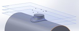
I am trying to add a line of rivets along a curve driven pattern but for some reason the rivets are not in line with the projected curve when I use the tool. They have followed the profile of the bottom of the chimney but when viewed from above they are not centered on the line. The rivets have also staid on the plane they were created on and are not seated on the bottom of the chimney. This is not so much of a problem because I could always lower the plane they sit on until they touch the bottom of the chimney. Could someone please tell me what I am doing wrong or is there another way of doing this. I look forward to any replies.
 

Attachments

  • 1.JPG
    1.JPG
    37.9 KB · Views: 5
  • 2.JPG
    2.JPG
    44.1 KB · Views: 5
  • 3.JPG
    3.JPG
    13.7 KB · Views: 5

michael080

Western Thunderer
Thomas,

I wonder how the rivets were placed at the prototype. I guess they are placed evenly spaced with 45° between them on a cylinder in line with the chimney perpendicular to the boiler surface. Also, they were drilled perpendicular to the surface of the boiler.

Try to find the intersection line between the chimney cylinder and the boiler cylinder. That line should be looking like a saddle..
Place 4 planes through the center line of the chiney cylinder evenly spaced with 45° distance. The intersection between the saddle curve and the planes should be where the rivets sit.

I didn't try it yet, but hope to find some time this evening.

Michael
 

michael080

Western Thunderer
I could figure out a way to design the rivets at the right spot.

First step: drae a circle perpedicular to the chimey axis with the diameter of your rivets. Split it into the expected number of rivets evenly around the circle. Put points at the intersection.
Screenshot (11)_cr.png

Start with a 3d sketch and draw a plane perpendicular to the boiler axis through the point of the first rivet projection. I hav emarked the point in blue.

Screenshot (12)_cr.png

Start a 2D-sketch on the newly defined plane and plumb down from the initial point to the intersection between boiler and chimney. Draw a line from the center of the boiler to the intersection point. This line will be the base for designing the rivet.

Screenshot (14)_cr.png

This is a 3d-view of the step above.


Screenshot (15)_cr.png

Design you rivet as desired.


Screenshot (16)_cr_cr.pngScreenshot (17)_cr.png


Screenshot (18)_cr.png

The rivet appears where I think it should sit. The rivet centre axis is correct.

Screenshot (20)_cr.png

Voila :)

I learned that 40 years ago at university where we had to draw these and much more complicated design on paper with china ink. Didn't expect to need it ever again :)

Michael
 

AndyB

Western Thunderer
I assume you can project points onto a surface in Solidworks?
If so, I would start as Michael has done with the circle and points

1740468131211.png
then just project the points onto the surface of the dome base. Saves creating all the extra planes and arcs.

Just check the projection method - must be in axis, not normal to surface.


I use FreeCAD - very good video on doing this kind of thing using other techniques on model aircraft parts here - night give some ideas for other CAD tools too.
Andy
 

simond

Western Thunderer
Michael,

nice solution. From your earlier post, I imagined creating the rotation of the rivet on a plane through the axis of the chimney and the point you created in step 3 above rather than the transverse plane you created in step 2.

I am now trying to work out in my head whether it makes any difference.

part of me thinks that it will, if the flange of the chimney is not a saddle of constant thickness, but some form of saddle-fillet.

I think I’ll have to draw it too…

(they never let me play with ink, I already made too much mess with pencils :)) )

cheers
Simon
 

simond

Western Thunderer
I assume you can project points onto a surface in Solidworks?
If so, I would start as Michael has done with the circle and points

View attachment 234620
then just project the points onto the surface of the dome base. Saves creating all the extra planes and arcs.

Just check the projection method - must be in axis, not normal to surface.


I use FreeCAD - very good video on doing this kind of thing using other techniques on model aircraft parts here - night give some ideas for other CAD tools too.
Andy

As far as the points are concerned I agree and I’m sure Michael will also, but that does not automatically give you the axis for the rotation that is needed to create a rivet.

Of course, if the rivet head is simply the bit of a sphere that protrudes through the surface of the saddle, it doesn’t matter

If, otoh, you wish to have a hex head, or a recess into which the head may sit, it might.
 

michael080

Western Thunderer
I assume you can project points onto a surface in Solidworks
If so, I would start as Michael has done with the circle and points

It is quite likely possible to project points, but it was a bit early. I couldn't figure out how. :confused:

My approach is more like a brute force thing.

As far as the points are concerned I agree and I’m sure Michael will also, but that does not automatically give you the axis for the rotation that is needed to create a rivet.

I tried that yesterday evening, but I didn't like the fact that the rivets were parallel to the chimney and not pointing towards the boiler center line. Also, I couldn't figure out how to determine the point where the projection intersected the saddle.
 

paratom

Western Thunderer
Ok I think I have worked out the easiest way of doing the rivets. There should be 8 of them and they should be offset by 22.5° from the loco centre line.
1a.JPG
I use the Curve projection tool to project a curve onto the surface of the chimney. The blue circle is sketched on another plane.
1b.JPG
This blue line is where my rivets will sit.
2a.JPG
The pink rivet is the seed drawn 22.5° from the loco centre line. The mistake I made was not to draw this rivet on the surface of the chimney.
2b.JPG
Used the semi circle tool sketch my rivet.
2c.JPG
Then used the Revolved Boss/Base tool to create a sphere.
4.JPG
I finally used the CrvPattern tool to add the rivet to the projected curve. Revolve1 is the rivet I created using the revolve tool.
4500 Straight Copper Topped.JPG
Here is the final chimney. I've had to increase the size of the rivets slightly after 3D printing the chimney as they hardly showed up in the first print. Sometimes in 4mm you have to over scale things slightly for them to be seen which can vanish once a coat of paint has been applied. Finally got there in the end.
 

Attachments

  • 1.JPG
    1.JPG
    15 KB · Views: 0
  • 1a.JPG
    1a.JPG
    23.1 KB · Views: 0

J_F_S

Western Thunderer
Just while we are rivet counting ... I should mention that snap-head rivet heads are not hemispherical (otherwise, you could not knock them down) - this might (or might not!) explain why they looked undersized in the print. Many RTR models are marred by this as it sticks out a bit once you know about it as hemispherical rivets look too prominent.

It does make placement a bit more tricky, but no worse than it would be if these were hex bolts - which they sometimes are.

Best Wishes,
Howard

1740501277407.png
 

adrian

Flying Squad
I use FreeCAD - very good video on doing this kind of thing using other techniques on model aircraft parts here - night give some ideas for other CAD tools too.
I've been using FreeCAD to learn a little more on the 3D modelling side. So far I have managed with basic shapes and components reasonably okay where I've been adding and subtracting boxes and circles etc. However I've been struggling to get a satisfactory blend on the dome to the boiler from the tight radius at the top to a larger radius for the sides. I've tried some of the guides about lofting along a curve but can't seem to get a path defined for it to follow accurately. Any pointers to some useful guides would be appreciated.
 

Brian McKenzie

Western Thunderer
I'm not a FreeCAD user, but you may be able to project a circle on to the surface of an extruded boiler.

Refer first two images of @paratom's #8 post above

Then on the plane you use for the side of the loco (I use Front plane for this, Left plane for the front of the loco, and Right plane for backhead end), draw the small radius where a dome meets the top of the boiler. Then on either Left or Right plane (as per my usage), draw the larger radius (or shape) for where the side of a dome extends down the slope of the boiler side.

Trim all the lines so that you are left with a 90degree segment of the full skirt required. Ensure that these lines are properly connected to each other.

Loft lines will be those last two radiused lines drawn, and the Guidelines are a quarter of the circle (that used to project the initial circle), and the line generated sweeping downwards on the boiler surface.

You may need to select options as to how the two Loft lines project from their planes.

Mirror this surface to go from 90degrees to 180degrees, then mirror all of that again to get the full 360degree wrap.

(Done hastily from memory E &OE ;) )

-Brian McK.
 

michael080

Western Thunderer
As we are talking about Solidworks, they are promoting a "maker" license for individuals that is only 24USD per year. In case somebody wants to play "with the big boys", I think this is pretty good compared with the license price my company pays.

Power the Maker Within

Obviously, I am a happy user nut not affiliated in any way.

Michael
 

paratom

Western Thunderer
For the first year, then the subscription doubles.
Where did you read that the price doubles ? Even at double the price it’s still a bargain. Fusion 360 paid version is £660 a year. The only downside of the Solidworks Maker licence is you are not allowed to generate more than 2000 dollars a year in revenue from it but that shouldn’t be a problem for the hobbyist. I haven’t done a comparison between the two but Solidworks seems to be more of a high end package that industry uses. I might give Fusion’s free version a go and replicate what I have made in Solidworks.
 
Last edited:
Top