4mm The Harboro Stone Co.

Dave

Western Thunderer
Evening all,

I started to build this new micro layout a few months ago, so I thought I may as well start a thread about it.

Scale: 4mm
Dimensions: 4ft. x 18 ins. plus 18 in long FY.
Time Period: 1950s/60s
Location: Peak District.

It is a fictional location and company, somewhere around Wirksworth/Cromford/Matlock. A limestone processing plant that is connected to British Railways and to a distant quarry. I like to make life difficult for myself, so decided that the line to the quarry was originally narrow gauge and was converted to standard gauge during The Great War. This means the line has a tunnel with very restricted clearances and can only be worked by engines that have been specially adapted. The BR connection was put in by the Midland Railway and is of a conventional loading gauge.

Loads out consist of crushed limestone for use in steelmaking and as roadstone. This is carried in hoppers and tipplers. Limestone dust, for various uses including fire prevention in coal mines, leaves the site in Presflo and Covhop wagons.

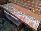
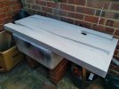
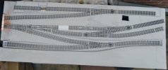
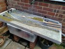
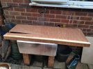
The baseboard.
20220617_115935.jpg

20220617_175623.jpg

20220622_182420.jpg

20220628_120828_1.jpg
The FY bolts on to the LH end and the lowermost track goes to the quarry. The white patch on the run-round loop is the weighbridge and the hole in the baseboard near the top RH is where wagons of quarried stone will discharge. The top LH track is where the engine shed will be sited. The gap in the sleepers there is for an ash pit.
 
Last edited:

2996 Victor

Western Thunderer
Great start on what looks to be a very interesting project! Are you planning a working incline?

Thanks for posting - I'm looking forward to following your progress.

All the best,
Mark
 

Dave

Western Thunderer
Thanks, chaps.

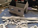
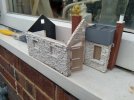
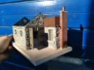
There will be only three buildings on the layout, the processing plant, the weighbridge and the engine shed. I started on the engine shed a just over a month ago.
20220704_174303.jpg
I made a shell from mounting card and then rolled lots of DAS clay into flattened sausages before snapping off individual stones and assembling them into walls.

20220708_191012.jpg
The doors were made from plywood, the door frame from coffee stirrers and the water tank from Plastikard. The window frames are laser-cut, from York Modelmaking.

20220709_184450.jpg
Since the above photo I have added louvres to the end ventilation openings and have the roof partly done.

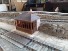
The weighbridge has been constructed in a similar manner but with parts of a Wills conservatory kit for the windows and doors.
20220716_162505.jpg

In the previous post I said that the main line connection would have been built by the MR but of course Harboro was on the route of the C&HPR. I don't suppose it matters as its pure fiction anyway.
 

2996 Victor

Western Thunderer
Fabulous work on the buildings - just the right amount to emphasise the remoteness of such locations. Beautiful and understated modelling, very atmospheric.

In awe,
Mark
 

Dave

Western Thunderer
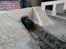
Thanks, chaps. It is tedious but I think it's worth the effort. It isn't only the two buildings that I've made from DAS stones but the retaining wall, bridge support and tunnel entrance too.

1659796813072.png

20220720_171636.jpg
I used a Wills arch to finish off the tunnel entrance. This photo shows just how tight the clearances are with the engine's cab only just fitting. This is a Hornby W4 Peckett that has already had the footplate dropped and boiler fittings cut down but the chimney needs to be lowered by another couple of millimetres and the safety valves need to be placed inside the dome cover for it to clear the crown of the arch.

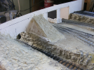
The rock faces were made by pouring Plaster Of Paris into a Woodland Scenics mould but in the case of this area of the cutting the depth of the castings was too much and thinning them down nigh on impossible. To make thinner rock faces I used yet more DAS. It was rolled flat and pressed into the mould and although it doesn't take the detail as well as plaster, it is good enough and allowed the parts to be made thinner. The alternative would have been widening the cutting and I couldn't face more woodworking.
20220710_152128.jpg
 

Dave

Western Thunderer
This post brings us up to where I am with the layout at the moment with a quick mention of the electrical bits.

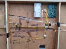
In the past I have used point motors on layouts but for something so small they're simply not neccesary as mechanical controls are all within easy reach. I have used turned brass knobs and piano wire, routed through electrical connector blocks to act as stays. It's a system that worked well on two previous layouts but on those the end of each length of wire pressed on the arm of a microswitch to change the frog polarity. As I no longer run DC at all I fitted a 'Frog Juicer' to take care of the frog polarity on all six points. I change the points by pulling or pushing the brass knobs and the juicer does the rest by some sort of magic.

I used copper tape for the DCC 'bus' and the DCC unit itself is a PIKO Smartcontrol Light. It looks a mess but it works and you're not supposed to see this bit anyway.
20220714_110340.jpg

And the right way up.
20220805_111008.jpg
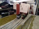
The dead end sidings that have not yet been ballasted are where the processing plant will go. The idea is to have a working loader here.
The flat foreground area will have a low-relief workshop at the far right. So that's where I'm up to at the moment. Exciting, innit? :)
 

Dave

Western Thunderer
I'd like to pick the brains of the techy sorts on the group, if I may?

I have made a start on the main building, which is to feature a working loader. I have made one of these before but it was a pain to operate - literally! I had to bend over and peer into the gloom to watch the load flowing into each wagon and cut off the flow before it spilled over. This time I want to use one of two options.

Devise a way of allowing no more than a single wagon's worth of load to be dispensed at a time so that I don't have to watch it or...

Monitor the loading by a tiny camera that somehow sends the image to my mobile phone. I don't know if such a thing exists but I guess anything's possible these days?
20220807_175415.jpg
Regarding the appearance, the areas that are still plain card will be covered with a corrugated iron effect and the parts that are hanging in mid air will be supported on H columns. I was going to use plastruct but it's not very robust, so I may opt for milled brass sections.
 

2996 Victor

Western Thunderer
Being a confirmed luddite, I've been trying to think of a mechanical solution.

All I can come up with thus far is a form of friction drive such as you find in cat toys - pull the mouse's tail and it runs along the floor for a pre-determined length of time. You could adapt it to open a spring-loaded hopper door to allow stone to drop, the hopper door being self-closing as the friction drive runs down.

Camera-wise, what about one of those doorbell camera thingies that talk to your phone?

Cheers,
Mark
 

Dave

Western Thunderer
Camera-wise, what about one of those doorbell camera thingies that talk to your phone?
Thanks, Mark. Being a confirmed tight-fisted Yorkshireman I have just Googled them and said Ow much??? :D

My thoughts on a mechanical system involves a revolving tube with an opening along its length, placed under a hopper. When the opening faces upwards the tube fills with material. Rotating the tube until the opening faces downward allows the material to fall out into the wagon below. The tube is of course made with an internal volume that matches that of the wagon. In theory that would work but in reality it may be somewhat different. I guess a lot depends on the materials used to build it and how powerful a drive system is to operate it. I'm thinking here of bits of stone being trapped etc.
 

2996 Victor

Western Thunderer
To be honest, I had no idea how much those doorbell things are! As you say, "Ow much?" Robbery with violence springs to mind.....

Would an Archimedean Screw have any merit? If it were motorised and the motor's on-time timed(!) to deliver a wagon load's worth of stone?

My brain's fried - I'm off to the bar.....

Cheers,
Mark
 

simond

Western Thunderer
I would definitely work on the “measured amount” approach, were I trying to develop a motorised loader. The question is then one of how to fill the measure, which can be done to excess, as the extra will then fall back in the tray.

If you do it manually, that might be a simple solution
 

Osgood

Western Thunderer
Mark's Archimedean screw has merit - an open screw set in the sloping side of a hopper pulling material out of a hopper in an open top U-shaped tube should work well, and varying speed and duration of rotation gives good volume / load rate control.

If wagons are all same capacity, how about a 'magazine' of cylinders, like the cylinder of a revolver pistol rotating in a vertical plane above a loading chute (the pistol barrel) of same diameter as tube?
As each wagon presents for loading simply index the magazine around to allow the next cylinder to empty.
If the cylinder rotates at a constant speed the flow will start low, then increase as the exposed circular area of the tube over the chute gets bigger - the rate of loading being controlled by magazine speed.
Interface between magazine and 'floor' needs some thought (cylinder/floor plate material choice) to ensure no jamming, but if slightly sprung-loaded it shouldn't be a problem.
Refill in bulk (except the cylinder over open chute) when all emptied.
Given the height of the building you could have a large number (7 or 8?) of small diameter tall cylinders whose diameter matches the chute diameter, so no risk of bridging.
Smiley popcorn lge.gif
 
Last edited:

Phil O

Western Thunderer
On the camera front, have you considered getting a reversing camera kit, these come with their own screen and plenty of cable, you will need a 12volt dc supply.
 
Top