The Heybridge Railway, 1889 to 1913

Richard Gawler

Western Thunderer
DSCF3456.jpg
I think, the 40W iron is on the limit for laminating sheet parts together. I could tin a strip about 5mm wide all around the inner faces (like drawing a box with solder) easily enough, and try to sweat them together, but the solder didn't run out to the edge as I expected it would. Perhaps my tinning was too thin. So I ran in extra solder from the outside edge, this was drawn into the joints by capilliary action. Except where the joint was already full, like above.

DSCF3486.jpg
The parts I had made up so far then went together rather nicely.

DSCF3487.jpg
This shows how the outer side folds underneath before the solebar (also an L shape) goes on below. Clever design really.

DSCF3405.jpg
You have to reduce the height of the cross-ways internal partition as well, about 0.5 mm to take off. So I used a scrap of fret to gauge the amount to remove.

DSCF3458.jpg
I think next time I would solder the two layers together and then take off the 0.5 mm. You have to alter one of the tabs as well and here you can see I forgot to do one side on the tab nearest the camera.

DSCF3518.jpg
At the ends of the solebars, the part folds up to make the dumb buffer. I ended up with gaps on all four of these because I wanted the four sides to be square to each other.

More pics to follow ... please do say if this is too simplistic for WT. I do hope to move on to more complex models when I have go the hang of this :)
 

Richard Gawler

Western Thunderer
With the cross-ways partition soldered in (see next installment!) I added the corner strapping. The strapping seems quite intricate because each corner has two pieces of strapping. I would have thought a single piece with a half-etched bend line would be easier, but then again I have never designed a kit. So I expect the designer had a Reason for this.

DSCF3495.jpg
The offcut of aluminium angle is helping me align the first piece flush against the side of the body.

DSCF3521.jpg
Eventually, the second piece went on. I was pleased but slightly over-did filing the radius between the two plates.

By now I had solder filling the gaps in the dumb buffers, but not quite enough and I ended up adding Milliput lest I disturb other parts.

DSCF3530.jpg
For the subsequent corners I tinned a strip along one side of the strapping and relied on the excess solder on the corner joint of the wagon to fix the strapping.

DSCF3532.jpg
I had a quick exchange of emails with Jim McGeown and he suggested a crocodile clip. This grips better than the bulldog clip. So - crocodile clip on one end, point of scalpel blade pressed down on the other end, and soldered up. I had tried the scalpel blade on its own but the strapping just swivelled around.

DSCF3534.jpg
With the second piece of strapping in place it is easy to add some solder if needed along the outside corner and then add a radius with the file.

The pinkish stain formed on only these parts, I have no idea why. All of the parts are from the same etch.
 

simond

Western Thunderer
The pink is copper. This probably happened when the flux “etches” the brass & dissolves the zinc. It’s not an issue (unless you dissolve detail away) and will probably polish away when you scrub the model with shiny sinks or cif.
 

Richard Gawler

Western Thunderer
The corner strapping parts are half-etched. Perhaps my flux reacted with a residue remaining on the parts after manufacture. Yes the copper washed off with soapy water and the strapping returned to its original brass colour.
 

Richard Gawler

Western Thunderer
I made a proper schoolboy mistake when I soldered in the cross-ways partition. I pulled the model onto a slight twist to make sure the partition fitted really neatly at the top. And it looked really neat too.

DSCF3547.jpg
So I went through the corner strapping in complete innocence until I returned the model to my glass picture frame which is my attempt at a plane of reference. I made my correction in one of the axle guards, I opened up the hole so the wheel bearing could go in a bit low.

DSCF3556.jpg
I tacked the axle guards in with 145 solder and then set them in Araldite. The first three are easy enough of course. In spite of a special effort with the fourth one, the wagon still has a diagonal rock on its wheels. This is about four but not five thicknesses of budget kitchen baking foil so about 4 thou. Arguably, only I can "see" it - the wagon runs fine.

This kit originated from Majestic Models. I cut the rectangle from the etch to see how well I could cut a rectangle, to see how well I could attach a part with access to only one side, and to hide two unwanted slots in the floor. Like many things it looks better under its primer.

DSCF3559.jpg
I quiite impressed myself with the stantions for the footboards. I had left them off until after fitting the axleguards so I could make their installation look symetrical, but this made it impossible to get at the backs of the stantions to reinforce them. So they tend to bend inwards if I pick up the model too roughly, but this look is probably prototypical.

DSCF3578.jpg
I used Araldite for all of the whitemetal castings except the builder's plates, which went on with cyano.

I have omitted all of the brake gear to emphasise my period. The brake on the locomotive should be enough.

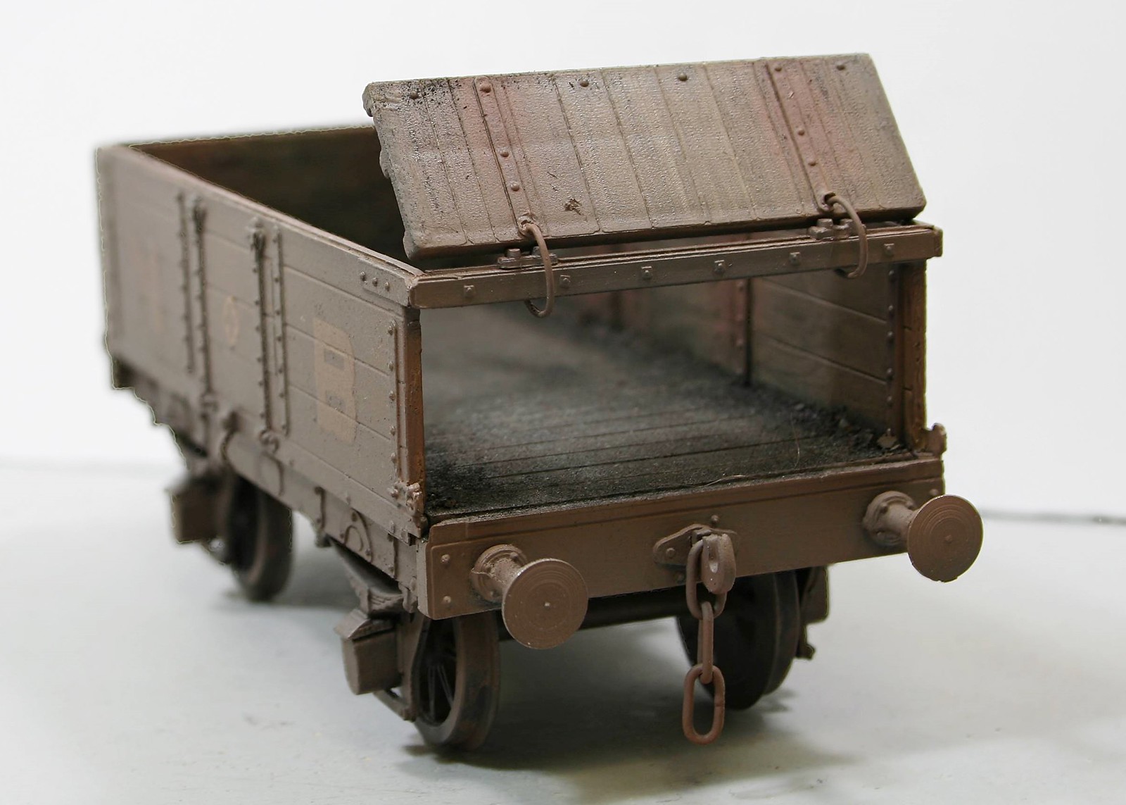
The hook at one end is three laminations soldered together and filed to shape. I tried to do the same at the other end but my enthusiasm ran away and I cut the shanks off all three hooks. So this end received a single thick brass hook from somewhere else.

Then I went over all of the nooks and crannies I could see with Milliput.

DSCF3591.jpg
I sprayed a coat of U-Pol number 8 "acid etch primer" (rattle can from Halfords), tidied up a few obvious lumps and bulges and then added a second coat. It seems best to apply a coat thick enough so it stays looking wet for five minutes or so. I don't know how it works but it bonds really well, I have a test piece and I cannot pick off the primer with a finger nail as hard as I try. I need abrasive paper to scratch it.

I masked the tyres of the wheels with tape but everything else got a coat of the primer. It seems to stick to everything except acrylic and enamel paint, which it dissolves rapidly when wet. Just don't ask.

This is the end of the build. I want to keep the wagon in primer for a while. I have a Connoisseur kit for a starter loco to build (this will be my first 7 mm loco kit) and hopefully the two will run together.
 
Last edited:
NBR 'Jubilee' coal wagon (1887 style)

Richard Gawler

Western Thunderer
DSC_9382.jpg
This is a North British 'Jubilee' coal wagon from the Peco / Parkside kit with the solebars exteded to make dumb buffers.

DSC_9380.jpg
Some of my wagons get painted underneath and some do not. The ballast weight is 2 mm roofing lead.

DSC_9385.jpg
I was pleased with the end door. I put a scrap of paper under the bottom edge when I glued it on to leave a tiny gap and it does look like a door and not a fixed end with hinge details.

DSC_9386.jpg
I painted the model with Revell enamel no.43 "USAF Gray" because I had some of this to hand. The ironwork is Tamiya 'Dark Iron' and the inside walls are Humbrol 'wood'. The floor is a laser-cut panel from Poppy's Woodtech and this is still unpainted at the moment.
 
Last edited:

Richard Gawler

Western Thunderer
:)) :)) yeah I bet that was said plenty of times in reality back then - until the day it wasn't... :rolleyes: :oops: :shit: :)
The decision to omit the brake gear on the tender truck was difficult because the castings in the kit are first-class and they would have fitted really well. However, the background information I had suggested either brakes on both sides or not at all. Nearly all my wagons have brakes on only one side and it seemed excessive to make this wagon, ostensibly one of the oldest things on the railway, the best-braked.
 
Last edited:

Overseer

Western Thunderer
View attachment 164291
This is a North British 'Jubilee' coal wagon from the Peco / Parkside kit with the solebars exteded to make dumb buffers.

View attachment 164290
Some of my wagons get painted underneath and some do not. The ballast weight is 2 mm roofing lead.

View attachment 164292
I was pleased with the end door. I put a scrap of paper under the bottom edge when I glued it on to leave a tiny gap and it does look like a door and not a fixed end with hinge details.

View attachment 164293
I painted the model with Railmatch 'Diesel Roof Grey' because I had some of this to hand. The ironwork is Tamiya 'Dark Iron' and the inside walls are Humbrol 'wood'. The floor is a laser-cut panel from Poppy's Woodtech and this is still unpainted at the moment.
To be pedantic, the 8'6" wheelbase Jubilee wagons were only ever built with sprung buffers. The dumb buffer version from 1886 had a 7'6" wheelbase and were a foot shorter. All of the difference in length is in the side doors so chopping 7mm out of the centre of the sides produces a very accurate model, see one I did earlier here #23 (if the link works). The kit as it comes is an accurate model of the 1896 version of the NB Jubilee wagon. Not sure if the Jubilee name is from the Golden Jubilee in 1887 or the Diamond Jubilee in 1897. Apt model for this weekend. There is a GA drawing of the 1886 dumb buffered wagon in John Hooper's North British Wagons book.
 

Richard Gawler

Western Thunderer
To be pedantic, the 8'6" wheelbase Jubilee wagons were only ever built with sprung buffers. The dumb buffer version from 1886 had a 7'6" wheelbase and were a foot shorter. All of the difference in length is in the side doors so chopping 7mm out of the centre of the sides produces a very accurate model, see one I did earlier here #23 (if the link works). The kit as it comes is an accurate model of the 1896 version of the NB Jubilee wagon.

This could be embarrassing . . . BRM have just accepted my write-up of the build for their August issue :eek:

I have lightened this photo to show the markings on the rule more clearly:
DSC_9449.jpg

Yes the wheelbase scales at 8' 6". I am happy to learn about other mistakes or perhaps better "deviations from the protoype". I expect there is time to add a caveat somewhere in the copy.

I built the model in March and I wasn't thinking about our Platinum Jubilee at the time but I did save posting the pics for yesterday :)
 
Last edited:

Richard Gawler

Western Thunderer
Not sure if the Jubilee name is from the Golden Jubilee in 1887 or the Diamond Jubilee in 1897.

The kit instructions (which I realise can be fallible) say 1887, with construction from then until Edwardian times by the NBR and private wagon builders.

I hope it is 1887, because the model helps to set my scene in the 1890s and 1910s. I am imagining, the wagon came to Essex with a load of specialist coal for the iron smelting works at E H Bentall and arrived with some kind of damage or defect. The owner had had problems with this wagon before and agreed to sell it to the Heybridge Railway to save the cost of arranging repair and sending it back. I have no idea whether this sort of thing happened but imagination can be a fine thing. I picked out the ironwork in black to try to emphasise a change of ownership.
 

Rob R

Western Thunderer
Richard,
Apart from the "scottish" style end door, it passes very well for one of the many thousands of nondescript 19th century mineral wagons.
I may steal the idea for a future project..
Rob
 

Richard Gawler

Western Thunderer
Apart from the "scottish" style end door, it passes very well for one of the many thousands of nondescript 19th century mineral wagons.
I may steal the idea for a future project..
There is a hidden benefit in that every time I build up a plastic kit with dumb buffers I gain a set of four sprung buffers. These might be useful to replace cast ones in other kits.
 

Rob Pulham

Western Thunderer
Hi Richard,

I like your idea of a sip of paper to make the door look like it make open. If you build another it is possible to make the end door open

44472621521_46e12c971d_h.jpg


43754451534_7721477b28_h.jpg


I replaced the plastic rings with ones made from brass rod.
 

Richard Gawler

Western Thunderer
Rob it looks like you have used some Microstrip to add the steel strips on the top planks? And another brass dressmaking pin to hold a door spring, I guess the spring is from brass? And either you have made a neat job of the two hinge brackets on the top rail, or you have made up some new ones.

I can see a personal "feature list" developing to try for a 7' 6" wheelbase one.
 

Rob Pulham

Western Thunderer
Hi Richard,

Yes to all, except that can't remember how I did the hinge brackets (sorry) I thought I had some construction photos but I can't find them if I have.
 

daifly

Western Thunderer
As for the photo's please click on the "full" image [ I've already done it for this post ] rather than the thumbnail. I keep looking for the setting to remove the thumbnail setting but unfortunately not found it yet!
@adrian - this might help:
Dave
 

Jordan

Mid-Western Thunderer
More pics to follow ... please do say if this is too simplistic for WT. I do hope to move on to more complex models when I have go the hang of this :)
I must have missed this bit first time round. :rolleyes:
I would venture that there are some things that might be "too simplistic" for WT - pictures of how to open an R-T-R box*, maybe - but NOT soldering & building etched brass, however basic or advanced the kit involved. ;)

* A sport I am quite good at, but I don't post pictures of the process!! :oops: ....but if the model inside the R-T-R box is worked upon, or weathered, or suchlike, that is not too simplistic for WT either. :)

Meanwhile congrats on getting this into BRM. :thumbs:
 
GWR Hydra (1908) . . part 1 build

Richard Gawler

Western Thunderer
40W might be a bit light for 0 gauge models, but much will depend on the mass of the bit.

I must have missed this bit first time round. :rolleyes:
I would venture that there are some things that might be "too simplistic" for WT - pictures of how to open an R-T-R box*, maybe - but NOT soldering & building etched brass, however basic or advanced the kit involved. ;)

Thanks . . . this gives me a prompt to slip from "Blue Peter" mode (where I have been since I started this account) into what is on my bench at the moment . . .

DSC_9454.jpg

This is Jim McGeown's GWR Hydra. The mass of brass here is about 45 g and the mass of the bit 12 g. The soldering here involves connecting two lengths of deck together end to end, laminating two pieces of side together (the second layer is hidden in this pic), and attaching the side to the deck.

To my mind, the 40W iron is fine to put all of these together, but I had the very devil of a job undoing two of my four bits of "spot tacking" after I put the side on with a gap between itself and the sloping deck. Quite difficult really; a prolonged application of the iron, a Stanley knife blade pushed in really hard and, eventually, freedom. The obvious solution is to make smaller tacking blobs and to look at what I have achieved after each blob, not after the fourth.

With the tacking done, the 40W iron is making enough heat and carrying enough solder to the job to let me solder up c.20 mm of seam at a time. I now have two bits for the iron: the original one, which is like the tip of a flat screwdriver, and a conical one, which tapers to a radius of perhaps 0.5 mm. I prefer the conical one because it lets me spread a narrower path of unnecessary tinning each side of the seam. I am putting the flux on with a budget brush, five for £1 from The Works.
 
Last edited:
Top