Back to work on the pug and the next job is the coupling rods which will need to be around once I start making the chassis. This was going to be another experimental job since I wanted to make them of steel and I hadn't cut steel before, and I wanted to try and avoid cutter breakage again. I had to spend two or three days using CAD to draw up the coupling rods. I didn't have any dimensions or drawings so I used a good broadside picture imported into Draftsight to work out the side elevations and had to do a bit of deducing to work out the thicknesses of the bosses.
I opted to try using 1/16" steel strip which I had lying about in the workshop - in fact lying about for well over forty years, got many years ago in a Ken Whiston bargain pack.
")
A problem that can happen when milling strip is that the resulting piece can warp because of stresses being released by the cutting process, so I was going to be on the look-out for that.
The chassis will be fully CSB sprung so the rods will have to be jointed and I chose to reproduce the actual jointing, the only difference being to make the joint a half joint rather than a forked joint which was what the prototype probably had.

The rear pair of roads were cut with not much problem, with a 2mm cutter doing the surfacing and a 1mm cutter doing the profiling. I also used the 1mm cutter to bore guide bearing holes which will be opened out for bushing later on.

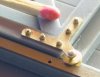
This was the setup and just starting to cut the front pair of rods. Lining up steel strip can be a bit of a fiddle since it is very rarely flat, hence the bits of paper to get it as close to flat as I could. I got it within .05mm along the length between the holding screws. The wood is used to give a sacrificial base to save the cutter when it breaks through.
Note the new, smaller ER11 collet head which makes things a bit easier when working around the clamping of small parts. Setting that up was a job in itself requiring drilling and tapping a rather hard Jacobs taper arbour which took almost a day with plenty of cursing.

The 1mm cutter cutting the profile of the second front rod. In between this shot and the shot above, I had gone through two 1mm cutters. The first one had done a fair bit of work - a lot of the previous cylinder work and both rear coupling rods, so it was probably getting blunt and carbide tends to break rather than bend when the stresses increase. The second cutter was brand new and lasted for about a couple of minutes, deciding to go ping at the first interrupted cut it came to. So I dropped the cutter feed and the third cutter worked fine.

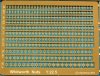
When all the rods were cut, I flipped the strip over and started the machining of the half joint recess on the rear rods - the recesses on the front rods had already been cut when machining the front of the rods. The cutter lasted about a minute after this picture was taken.
The tabs you can see which were holding the parts in place turned out not to be strong enough to hold things securely when this cutting was being done and the part moved and broke the cutter. Fortunately it had almost finished the cut so I was able to finish of the recess by hand with a needle file.
I cut the second recess with a different setup and a larger cutter and that worked well and will be the way I do this operation in the future.

The two sets of rods apart...

...and the rods (sort of) in position. I've still got a bit of finishing work to do and I need to get some emery paper to do it. The leading and trailing bosses on the bosses were flush with the rods on the prototype.
I know that milled coupling rods have been around for quite a while so I'm not exactly breaking new ground, but I suspect they haven't been around in the smaller scales since keeping small cutter breakage down means that cutter feeds have to be quite slow and cutting a set of rods would take a long time, so probably wouldn't be a commercial prospect. It would cut a lot easier using nickel silver but I'm not sure how nickel silver would look.
I'm now off to get some more cutters online.
Jim.
 ....... runs and hides behind wall with Heather .....
 .
.


 I hadn't broken a cutter for a very long time so it came as a bit of a shock. Two were down to me in not allowing for the cutters digging through waste material too deeply, but the other three just went "ping" when cutting at feeds and speeds which I had been using successfully for quite some time. I could only put it down to the brass being a bit tougher to cut - it was the first time use of a 2.5mm sheet I got many years ago and I now can't remember what grade it was supposed to be. So speeds and feeds were made a bit more conservative and things have gone well since then. Carbides cutter are extremely good and hold their sharpness for much longer than HSS ones, but they are so brittle that one false move and they've gone.


