Fitting a Digital Readout to my Sieg SX1LP Mini Mill

Rob Pulham

Western Thunderer
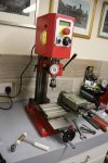
For my birthday last October I received a Digital ReadOut (DRO) kit for my Sieg SX1 LP mini mill. I fitted it over a weekend last October and although I took photos as I did each stage, I haven't yet got around to writing it up. Paul's posts (@OzzyO) on fitting a DRO to his mill prompted me to get my finger out so that anyone who is interested will get a couple of takes on fitting them to different types of mill.

As I am not anywhere in the same league as Paul when it comes to machining, my first port of call when looking was to YouTube. To see if anyone had done a video on fitting a DRO to a similar mini mill. I was quite surprised that at that time there wasn't any to be found (there may well be now as I haven't looked since).

Having realised that I was essentially on my own, my first port of call was to ring Arc Euro Trade whom I bought the mill from. To ask if they did a DRO kit for my mill. I was a little surprised that they didn't, as they seem to cater well with other accessories and tooling for the range of machines that they sell. Their recommendation was to talk to a company called Touch DRO who apparently do something suitable.

I have seen a few videos which featured Touch DRO units and confess that I was not keen on the idea. This is on the basis that they require the use of scales, which connect via Bluetooth to a tablet for the display. I spent 20 years in IT support and the last thing I want is yet another device.

Again on the basis of seeing a few videos on badged variants of the units supplied by Warco I opted to buy from them. I got a display reader, two x 100mm glass scales and one x 250mm.

The idea was that I would use one of the 100mm scales on the Y axis (front to back movement of the table for those unfamiliar with the axis terms) and the other for the Z axis which is the up and down movement of the mill head. This latter proved to be a mistake which I will elaborate upon later. The 250mm scale was to be used on the longer X axis table (which is what the LP designation of the model number refers to).
 

Rob Pulham

Western Thunderer
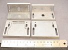
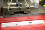
The Warco items duly arrived and each scale, came with a main rear mounting bracket and a pair of additional mounting brackets (Shown below) and a selection of M4 and M5 cap screws.

53685366748_135822d10c_b.jpg

Main mounting bracket.

53685475774_6b718d4ce2_b.jpg

These are the additional brackets that were spare as I only ended up using one of each along with some sections of aluminium angle which I had rescued from a set of shelves that I had dismantled.

To ensure that the job wasn't stopped for lack of drill bits if I broke any, I put in and order to Drill Services Horley for a couple of 3.2mm and 4mm drill bits. Of course because I had them to hand I didn't break a single drill bit.

All the holes drilled in the mill itself were done using a battery hand drill and being cast iron it was quite easy going if a bit messy.

The main mounting bracket holds the glass scale and then the read head is mounted so that when either the read head or the scale moves it reads off the distances. In my installation I have the scales mounted to the moving table axis and the read head's fixed to the machine bed. On the Z axis this is reversed and the scale is fixed to the column of the machine and the read head moves up and down with the milling head.

I decided to start with the Y axis as being one of the shorter ones so easier to handle and definitely the easiest to access on the left side of the machine. However as soon as I took the 100mm scale out of the packaging I knew that I had made a mistake in getting a second 100mm scale for the Z axis although it would be fine if I was working with the vice or rotary table mounted on the bed it wouldn't allow the head to come down far enough to mill anything directly mounted to the T slots of the table.

I immediately contacted Warco and explained my error and asked that since I hadn't opened the second scale, would it be possible to return it, and swap it for a 200mm scale. They were happy to do so and would sort out any additional cost incurred once they had it back with them. I returned it to the address on the signature of the person who had sent the invoice. This proved to be a mistake as it turned out that they had moved from that address so the package was returned to me. I called them and advised that there would be a delay due to my sending it to the wrong address which was on their email.

I looked at the actual invoice and noted their new correct address and re sent it there. As good as their word they very quickly despatched the replacement and didn't charge me a penny which despite my frustration at them not having the correct address on their correspondence I did appreciate.
 

OzzyO

Western Thunderer
Hello Rob,

thanks for the heads up, I've jut had a look at one of the company that's selling the bits like mine and I worked out the cost for your mill.
DRO X1 £106.21
100mm scale X2 £72.90 Individual price £37.58 X2 £75.16 so a discount of £2.26
250mm scale X1 £55.45
Total £234.56. Without the discount of £14.29
End total £220.27.

I don't know what you payed that up to you to say if you wish.

I'm having more fun fitting my first scale. I did think it would be easer than it's turned out to be. That's enough of me taking over Rob thread.

ATB

OzzyO.

PS. a 200mm scale @ £54.51.
 
Last edited:

Rob Pulham

Western Thunderer
Hi Paul,

Mine was almost £500 - roughly £200 for the display unit and £100 each for the scales actually just less but not much.
 

NickB

Western Thunderer
Rob,

I would class a DRO as the #1 upgrade to any mill. I've fitted them to both the mills that I have owned and it would be hard to do without them. It increases ease of use by a large factor, not having to compensate for backlash and count number of turns of the handwheel.

Nick
 

Rob Pulham

Western Thunderer
Hi Paul,

Mine was almost £500 - roughly £200 for the display unit and £100 each for the scales actually just less but not much.
I would add that had I waited a couple of months I could have got them all 30% cheaper but them's the breaks.
 

Rob Pulham

Western Thunderer
Rob,

I would class a DRO as the #1 upgrade to any mill. I've fitted them to both the mills that I have owned and it would be hard to do without them. It increases ease of use by a large factor, not having to compensate for backlash and count number of turns of the handwheel.

Nick
Hi Nick,

I agree, I confess that I did struggle for any real accuracy when using the mill prior to fitting the DRO. It wasn't helped by the table dials being calibrated in 0.025mm increments and the quill being in 0.03mm increments.

Although I have DRO's fitted to the lead screws on the compound/cross slide of my lathe. They work on the rotation of the leadscrew and I am not entirely convinced of their accuracy. Better than nothing but I plan to do something similar on my lathe at some point.
 

Rob Pulham

Western Thunderer
I mentioned that I started with the Y axis first

53676976977_f76425d89e_b.jpg

53676973942_af9f7056fb_b.jpg

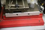
There was a convenient ledge on the side of the bed casting which allowed me to add a parallel to get the backing plate up to the right height to mark for drilling the mounting holes. The 123 block is just holding it in position.

53678301010_52659c2514_b.jpg

I added some engineers blue and marked the holes with a scriber then punched the centre.

53678065063_766ba457b3_b.jpg

Drilled, tapped and cleaned up with IPA

53678200609_a4df354011_b.jpg

The backing plate in place, so far so good.

53678062938_8e1676b7fe_b.jpg

A trial fit of the scale to work out where the reader needs to be fastened to.

53676969872_49e2559205_b.jpg

At this point I realised that I would need some packing pieces behind the mounting plate to make it stand off due to the useful ledge that I referred to earlier and allow the reader a clear track without being forced to run at an angle and to allow the fitting of the chip shield which didn't quite fit when flush against the table.

I used a slitting saw to cut down some sheet material which some bar stock had been attached to to stop it being bent in the post. It's quite interesting material in that it is two layers of thin aluminium bonded either side of some plastic material. Being layered it's remarkably strong and light and I thought it too good to throw away so it went into my useful bits box.

53676969057_d277e116f9_b.jpg

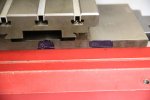
You can just make out in this shot where I slotted the vertical mounting holes in the angle bracket, again to allow the reader to track without adding undue pressure. You can also see the packing strip between the mounting plate and the edge of the table.
 

NickB

Western Thunderer
Hi Rob,

The DROs that Sherline sell for their machines use rotary encoders which don't overcome the backlash problem. I used linear scales instead, though it was a problem finding something small enough to suit such a small mill and figuring out how to attach them. One day I'll get round to a better display that shows three axes in one display.

Nick

IMGP1760.jpg
 

AndyB

Western Thunderer
For anyone who can solder and follow simple command line instructions for loading software, I can recommend the ESP32 solution from TouchDRO. It uses an ESP32 microcontroller to convert the outputs from any scale type to a Bluetooth signal that is displayed on a phone or tablet. In most home shops, only one machine is being used at a time, so why have a DRO display on each? With TouchDRO, you just take the tablet from machine to machine as needed. Each adaptor (per machine) costs <£20 to build.

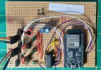
Whilst you can order the PCBs from the US, it isn't a difficult job to build it on veroboard. This is a 3-axis version:
DRO ESP circuit.jpg
More axes and a tachometer input can be added (needs another of the smaller IC's + input resistors, etc).
A 3D printed case completes the job; I've just installed the first one on my small milling machine with a second nearly ready to go on my lathe.
Usual disclaimer applies.

Happy to share my veroboard layout and stl files for the case if anyone wants them.

Andy
 

Rob Pulham

Western Thunderer
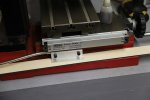
The next step was working out where to position the reader to get the full length of travel from it. I measured how much space the X axis scale would take up when fitted, added a couple of millimetres for clearance and used that as my forward limit. I then marked the base and drilled and tapped the base.

53678058603_33438db324_b.jpg

53690546710_3419e4f183_b.jpg

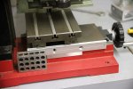
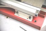
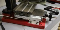
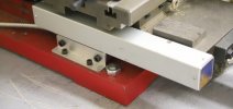
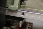
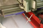
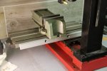
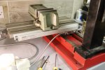
This is the Y axis scale fitted with it's swarf cover and working.
 

AndyB

Western Thunderer
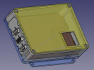
CAD model for the TouchDRO adaptor case.
USB-B micro connector for power (lower side), I'm using 9-pin D-sub connectors for the axis inputs, but they could be micro USB or whatever your scales / cables use. The connector plate just slides in so is easily changed.
1714552040355.png
The 'window' is glazed with a piece of clear plastic - it just enables the power LED on the ESP32 to be viewed so I know it is correctly powered up.
 

Rob Pulham

Western Thunderer
The X axis was a bit more involved in that it was harder to get access to even with the mill unbolted from the bench.

First job I found that the slots in the mounting plate were a bit tight for the M5 screws so I opened the slots with the mill.

53678058613_f39a61fb2b_b.jpg

I also milled the second slot to have vertical as well as horizontal movement as it's important to have the scales both level horizontally and parallel to the travel of the table for the highest accuracy. As they come one slot is vertical and the other horizontal but being aluminium they are easy to modify with the mill.

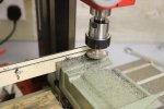
After bluing up the rear face of the table I was lucky in that I had recently bought a couple basic C clamps to use for clamping one of my vices and my rivet press temporarily to the workbench when I need to. These fit quite nicely edge on in the T slot so I was able to clamp the mounting plate in position allowing me to move the table to either side of the column so that I could mark it up without removing the table at this stage.

53678290220_03d80e808a_b.jpg

53678054533_14f8689d58_b.jpg

53676959622_3e7b107b31_b.jpg

Again, it was a bit of a squeeze but I was able to drill and tap the table without removing it.

53676958982_e1672dd79b_b.jpg

53676958097_dccdda0ca2_b.jpg

53678048248_350b268d5a_b.jpg

The next task was working out how best to mount the reader but I will cover that in another post.
 

OzzyO

Western Thunderer
Hello Rob, all,

Looks to be coming along nicely.

What does your scales read to 1um or 5um. mine reads to 5um that's about 0.005mm. The 1um reads to .0001mm.

You get the 1um scale at a cost, about 10-20% more.

ATB

Paul.
 

Rob Pulham

Western Thunderer
Hi Paul, mines to 0.005mm like yours.

What I did find interesting, having read it some where, is that all the read heads are produced in metric and if used in imperial mode, the measurement is still done in metric but the display does a conversion with inevitable rounding of the finer numbers.
 

Martin Shaw

Western Thunderer
Rob
With my tongue firmly in my cheek, why on earth would anyone want to do any measurement in imperial units anyway, especially in a hobby that uses mm to the foot as a scale?

I have a DRO from Allendale with magnetic scales, I think the number of times its been in inches is less than one hands worth of fingers and with 5 micron heads it cant really cope with less than a thou. If I could work to 0.001 mm tolerance I would be most happy and surprised.
Martin
 

Rob Pulham

Western Thunderer
Rob
With my tongue firmly in my cheek, why on earth would anyone want to do any measurement in imperial units anyway, especially in a hobby that uses mm to the foot as a scale?

I have a DRO from Allendale with magnetic scales, I think the number of times its been in inches is less than one hands worth of fingers and with 5 micron heads it cant really cope with less than a thou. If I could work to 0.001 mm tolerance I would be most happy and surprised.
Martin
I am right there with you Martin, I learned metric at school and I confess once you get lower than a quarter of an inch I am pretty much lost. It was just one of those things that I picked up. It was on a US site and they are still very much feet, inches, and thousandths...
 

adrian

Flying Squad
Rob
With my tongue firmly in my cheek, why on earth would anyone want to do any measurement in imperial units anyway, especially in a hobby that uses mm to the foot as a scale?
I'd say I use imperial 75% of the time and metric 25%. I just find imperial more intuitive and easier especially when marking out. Often I'm marking out the centres. So what's half of 7mm - easy 3.5mm - what's half of that harder 1.75mm what's half of that ... . Whereas what's half of 1/4" - easy 1/8" what's half of that - easy 1/16" what's half of that - easy 1/32" whats half of that - easy 1/64" and the ruler is all marked out for it. As always each to their own. :)
 

simond

Western Thunderer
solidworks makes life easy

You can type formulae in as dimensions and you can have constants

An inch in 7mm (fine scale or S7 ) is 0.5833 mm and you can do the feet and inches sums in your head so for example 1’2-and a half” is 14-and-a-half is 29 halves so type 29 * .5833 / 2 and so on.

I guess I could make the 1inch conversion into a global constant and then I could rescale anything I draw going forwards - would not help what I’ve done already though.

Can’t be doing with fractional inches, 23/64” anyone?
 
Top