Help required producing unusual buffers.

John Duffy

Western Thunderer
Following a recent conversation with a friend where we were looking at the need for some North British bolsters, I have managed to get the body parts prepared. Other fittings are available and the bolsters themselves can be fabricated. The one thing that I cannot see a way to produce is the buffer casing.

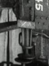
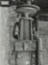
These were of extra length and had 4 fins, as per;

7C9E6B34-585D-4F1E-802B-0C80A94C4FA0.jpeg

There is a 4mm drawing available.

Would any of our 3D printing experts be willing to assist in producing these? Perhaps in exchange for some body parts in 4 or 7mm?

A1812505-1D2C-4C17-9939-EC278226B824.jpeg

Any help will be appreciated. DM if interested.

Thanks

John
 

simond

Western Thunderer
John,

the stocks appear to be “open”, that is the body of the stock is only the four fins, and the ring at the outer end, and the flange on beam. Is this your interpretation? I’m happy to draw something up and 3D print it, if you could give me a dimensioned sketch. I can’t currently help with the buffer itself, unfortunately.

Maybe there are better options!

atb
Simon
 

John Duffy

Western Thunderer
John,

the stocks appear to be “open”, that is the body of the stock is only the four fins, and the ring at the outer end, and the flange on beam. Is this your interpretation? I’m happy to draw something up and 3D print it, if you could give me a dimensioned sketch. I can’t currently help with the buffer itself, unfortunately.

Maybe there are better options!

atb
Simon
DM sent. Many thanks.
 

Osgood

Western Thunderer
I don't believe the buffer stocks would have been 'open', Simon.
The side loading on these in use is considerable and if open the strength would be reduced by I reckon around 85-90%.
Further the apparent line of the bottom of the buffer shank does not line up either side of what would be the outer ring of the stock in the photo.
The apparently loose D ring might suggest otherwise, but both sides are in the same location which suggests maybe a hole in the stock casting.
No, I believe Brian to be a conventional buffer - if a bit long in the tooth stock :D

Buffer stocks.jpeg
 
Last edited:

mickoo

Western Thunderer
If you're going to 3D print then I'd suggest making the barrel of the stock in brass and securing that to the headstock some how, easier with brass kits to be fair; then make the 3D bit with bolted flange slide over the top so it's cosmetic only and takes no load.

It's something I've been considering doing for loco buffers when the castings are poor.

This chimney follows the same principle, the print is quite fragile until the brass thin wall tube is inserted and then it's plenty strong enough.

IMG_2285.jpg
 

simond

Western Thunderer
mmm, Tony's argument is persuasive, the shank of the buffer appears thinner than the cylinder/tube between the fins, if indeed there is such a cylinder...

here it is to scale from John's drawing as an open stock.
1681734032848.png

and with an RCH buffer but with shank reduced to 2.5" installed.

1681734481348.png

and with the fins rotated o 45 degrees

1681734610625.png
I think this looks pretty much like the picture, though I have never seen such a buffer stock design

what does the congregation consider most appropriate?

Referring to Tony's estimate of loss of strength - are there signficant offset loads on a buffer stock? Buffing forces will be more or less axial, wagon loading, unloading and sheeting seem pretty negligible, I guess the only issue is if the wagon is craned by the stocks, which would seem likely at least on occasions.

John,

what do you think?


cheers
Simon
 

Richard Gawler

Western Thunderer
The open design needs its spring mechanism to be behind the headstock. This would make renewing a buffer unit more longwinded than usual. I think, the open design is a trick of the light in the photograph.
 
Last edited:

Osgood

Western Thunderer
Most certainly side loading.
If you have observed an industrial shunter pushing onto a load of stationary wagons the sideways movement is very considerable - can certainly be up to 6” lateral movement caused by the offset forces from the cylinders and connecting rods pushing the entire loco at an angle sideways on the rails, never mind the play in axleboxes, guides etc.
And just look at the number photos of industrial locos with broken buffer housings.

That said your renderings are quite persuasive too Simon :)) :rolleyes:
 
Last edited:

76043

Western Thunderer
Looking at the light reflection from the buffer shank compared to the reflection from the buffer housing, the latter would seem to be slightly bigger, indicating a regular type buffer. The far side buffer seems to confirm this to me.

Tony
 

John Duffy

Western Thunderer
mmm, Tony's argument is persuasive, the shank of the buffer appears thinner than the cylinder/tube between the fins, if indeed there is such a cylinder...


Referring to Tony's estimate of loss of strength - are there signficant offset loads on a buffer stock? Buffing forces will be more or less axial, wagon loading, unloading and sheeting seem pretty negligible, I guess the only issue is if the wagon is craned by the stocks, which would seem likely at least on occasions.

John,

what do you think?


cheers
Simon
From what I can see from the measurements, the barrel of the casing is not a parallel tube but tapers slightly from the headstock end outwards. It looks like the fins are similar in being slightly deeper at the wagon end.

Many thanks to everyone for the contributions and the offers of assistance.

John
 

simond

Western Thunderer
Rob, thank you, your first picture confirms what Tony said yesterday.

My artistic renderings are undoubtedly lovely :) , but wrong, tant pis. It’s not a big job to alter them, happily.

John, please can you confirm the shank diameter of the buffer itself?

If I have time tomorrow lunchtime I’ll see if I can’t improve on the efforts of today. It’s a pleasant distraction from the more usual office activities!

atb
Simon
 

John Duffy

Western Thunderer
Rob, thank you, your first picture confirms what Tony said yesterday.

My artistic renderings are undoubtedly lovely :) , but wrong, tant pis. It’s not a big job to alter them, happily.

John, please can you confirm the shank diameter of the buffer itself?

If I have time tomorrow lunchtime I’ll see if I can’t improve on the efforts of today. It’s a pleasant distraction from the more usual office activities!

atb
Simon
Simon, the buffer shank is 1.8mm.

John
 

John Duffy

Western Thunderer
Looking closely at some of the feedback and info that has been supplied I am now questioning the number of fins. The Tatlow drawing shows top and bottom plus left and right but the images don’t seem to bear this out. There is not a horizontal fin showing.

I am now wondering if there were 3 fins rather than 4.

Any thoughts?
 

Attachments

  • 9E22E3CE-E340-4066-A1B6-45C84E3FF1B3.jpeg
    9E22E3CE-E340-4066-A1B6-45C84E3FF1B3.jpeg
    189.4 KB · Views: 11
  • 37636282-4F27-4D28-86D8-A5215EFE9453.jpeg
    37636282-4F27-4D28-86D8-A5215EFE9453.jpeg
    215.1 KB · Views: 11
  • 7B331CED-0161-4103-8FD4-5094F6B66728.jpeg
    7B331CED-0161-4103-8FD4-5094F6B66728.jpeg
    118.5 KB · Views: 11
Top