MOVING COAL - A Colliery Layout in 0 Gauge

PhilH

Western Thunderer
There has been little progress on this layout since the last post 2½ years ago. Work on the Austerities was suspended due to eyesight problems (cataracts) and the delay in getting these remedied due to Covid. In the meantime attention turned elsewhere to things which didn't require perfect vision and with sight improved these still tend to keep me fully occupied. At the moment I'm lost in the wilds of Colorado (that's modelwise not literally !) rather than the South Lancashire Coalfield, but its all good fun, isn't it......? :rolleyes:

In earlier posts links were given and reference made to details of the layout originally posted on RMweb. However since the photos on there are lost (possibly never to return ?) the information given there is now probably of little use. I therefore thought it might be worth repeating some of the information here, particularly the wagon loading and unloading arrangements shown in operation in Post #20.

Starting with the loading arrangements at the colliery.


1. Track Layout.jpg

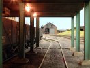
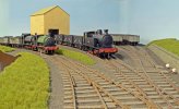
The normal method of working is as follows. Empties arrive on Track A, the engine runs round via Track B and then runs to the weighbridge/shed area ready for the next full train. If Track A is occupied the arriving empties use Track B and the loco draws forward into the siding to wait until the colliery shunter clears either Track A or Track B. The colliery shunter works the empties (left on plan) side of the screens collecting three wagons (the limit in the headshunt) at a time from the arrival tracks and propelling the wagons under the screens for loading.


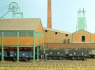
2. Screens 03B.jpg


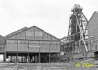
3. 14412B.jpg

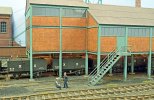
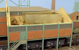
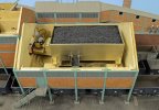
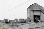
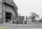
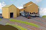
The screens are based loosely on the prototype screens at Ravenhead Colliery, St.Helens, which were somewhat larger and provided loading on 5 tracks. They were photographed after closure of the colliery with dismantling in progress.


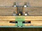
4. Column A.jpg

In anticipation of some form of mechanical loading the screen house construction was made fairly heavy and comprises a box of ¼" plywood supported on columns milled from square mild steel bar. Only the visible portions of the columns were fully machined to the 'H' profile, elsewhere they were just provided with a slot for the Plastikard cladding. The outside columns were silver soldered to steel plates which were bolted to the plywood walls, the bottom of the columns being machined with spigots to locate in the 'concrete' bases.


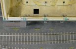
5. Overhead view.jpg

The spaces between the columns were filled with plywood panels and then faced with Plastikard brickwork, glazing and strip. I don't know whether the glazing would have been clear or opaque in the prototype but it would have been coated in coal dust on the inside so the plastic glazing was backed with grey paper. The square hole is for the future provision of loading wagons on the front track.


6. Column B.jpg

Interior columns are located in rectangular holes in the plywood floor at the top and by spigots into the bases at the bottom. Normally they would carry a layer of coal dust but that's been brushed off for the photo.


7. Screens.jpg

The higher rear section of the model screen building covers only two tracks for the simple reason I thought it would look more interesting. In retrospect it would probably have been more prototypical if it had been the full width of the building like the screens at Ravenhead. This higher section in the prototype would incorporate the tippler floor where the mine tubs were emptied.


8. Bickershaw Headframes.jpg

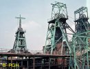
Colliery steelwork in Lancashire seems to have been predominantly light green, as shown here on the Bickershaw Colliery headframes, or light blue. The former colour was chosen for the model as otherwise the headframes would have been indistinguishable from the sky on the backscene.
 

PhilH

Western Thunderer
The screens load wagons on only two of the three tracks, the front and centre ones, and although the arrangements are slightly different the method of operation is the same.


9. Screens 1B.jpg

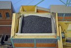
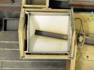
For the centre track the coal is loaded into a Plastikard hopper in the higher rear section of the screens, which holds enough to fill 9 or 10 wagons.


10. Screens 2B.jpg

The bottom of the hopper is tapered into a slot.


11. Screens 3B.jpg

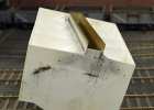
Viewed with the hopper upside down, below the slot is a vertical 'skirt' with an opening at the discharge end.


12. Screens 4B.jpg

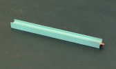
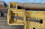
The skirt fits inside a trough, which is inclined at a shallow angle. There is approx 3mm clearance between the sides and bottom of the skirt and the trough.


13. Screens 5B.jpg

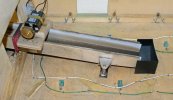
The trough is supported on 4 springs. On top of the trough is mounted a motor with an out of centre flywheel which vibrates the trough when operated. To the left of the motor is a rubber band stretched over the trough and anchored to the base which prevents excessive vibration of the trough.


14. Screens 7B.jpg

In this view the direction of rotation of the motor is anti-clockwise - that's fairly important. Operated that way all the material goes down the trough to the chute at the end for discharge into the wagons. Operated the other way half goes down and the other half climbs over the side and makes rather a mess. To control the loading of wagons the operator sits with the area under the screens at eye level. A battery powered miniature vacuum cleaner is very useful if mistakes are made !


15. Screens.jpg

The coal discharge chute for the centre track is at top left of the photo. The screen roads are at a slightly lower level than the main tracks alongside.
 

PhilH

Western Thunderer
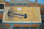
The loading arrangement for the front track is situated in the part of the building with a lower roof line and there wasn't room for a similar hopper plus vibrating chute, so the two were combined in a vibrating hopper.

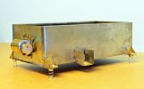
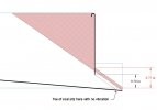
A sensible method for building the hopper would have been in Plastikard or similar material. However I had none of suitable size in stock, but what I did have was a large and rather tarnished sheet of 0.020" nickel silver which had been given to me some time ago, so I decided to use that. The hopper sits on 4 springs, one at each corner, and is vibrated by a 12 volt motor with an out of centre flywheel fixed to one end. Discharge is via a small opening and 'spout' at one side into a chute to direct the flow into the wagons below. To make the hopper discharge fully the bottom has to slope in all directions to the discharge point.

16. Hopper Section.jpg
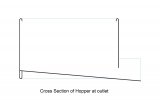
To give some rigidity the top edge of the sides and one end were turned over through 180 degrees. The bottom edge was also turned over but using more material which was shaped as required to support the floor. Thicker brass plate was used for the end to which the motor would be attached.


17. Screens detail 11B.jpg
Before fixing the motor tests were carried out with it temporarily clamped to the completed hopper and it was determined that fixed to the end as shown gave the best results, in effect vibrating the hopper up and down rather than side to side.


18. Hopper Outlet.jpg
The relationship between the height of the discharge opening and length of 'spout' is important, too big an opening or too short a spout would result in some of the contents of the hopper discharging without operation of the vibrator as shown in the sketch.


19. Screens detail 12B.jpg

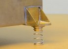
Brackets were provided at each corner for the springs, mounted top and bottom on turned brass spigots


20. Screens detail 13B.jpg

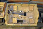
The springs were located on MDF blocks to raise the hopper clear of the existing trough feeding the centre road. The inside of the building is unusually clean because it has been thoroughly vacuumed to remove any coal dust from previous operations


21. Screens detail 14B.jpg


22. Screens detail 10B.jpg

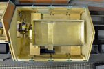
The Hopper in position


23. Screens detail 15B.jpg

Wired up and filled with coal ready for operation, the contents will comfortably fill 8 wagons.
Control is via a changeover switch between the two loaders and a DC controller to regulate the motor speed.
Next the unloading arrangements.
 
Last edited:

PhilH

Western Thunderer
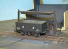
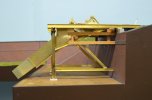
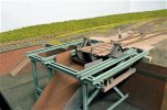
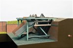
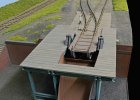
There are two wagon tipplers on the layout - a side tippler serving the coal washing plant and an end tippler serving the canal basin.

Inspiration for the side tippler came from the one at Mapperley Landsale Yard, Nottingham. The yard was at the summit of a half mile long incline from Gedling Colliery and served as the colliery's main outlet for bulk coal deliveries by road transport. NCB internal user wagons were hauled up the incline and tipped by a rotary tippler which fed a row of hoppers used to fill the lorries.


24. 34707B.jpg

This is a view at the top of the incline, looking away from the incline itself. On the left 3 full wagons have just ascended the incline, in the centre the diesel loco is propelling 4 empty wagons towards the incline top and on the right is the tippler with a wagon in the process of being tipped. The lengths of rail between the two tracks are for the incline rope to slide across as the wagons descend the incline.

25. 34710B.jpg

A closer view with a full wagon being run by gravity to the tippler. Part of the tippler mechanism is just visible inside the building including the beam which clamps the wagon to the table. To the right of the wagon is the conveyor leading from the tippler house to the road hoppers.
The advantages of this prototype in model form are the building would contain any coal dust generated during the tipping process and as most of the tippler mechanism is hidden the detail could be simplified. The exterior of the building has yet to be completed and I haven't decided whether or not to copy the asymmetrical roof line of the prototype or provide the exterior staircase. The tippler is intended to feed a coal washing plant to be constructed in the corner of the layout immediately behind.


26. Layout 12B.jpg

The Kerr Stuart FRANCIS shunts NCB internal use wagons into the tippler as a double headed train arrives with full wagons for exchange with BR. The empty wagons to the right wait to be loaded at the coal washing plant - when it gets built (they will probably have a very long wait !)


27. Layout 105B.jpg

A mock up of the washing plant in cardboard just to see how it fits into the corner, that's as far as its got to date. Ignore the pannier tank - its not mine !


28. Tippler Diagram.jpg

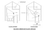
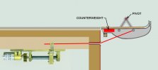
The operation of the tippler is shown in the above diagram. It basically consists of an 'L' shaped platform pivoted at the top of the vertical leg. The wagon sits on the horizontal leg and the platform is raised by a cable connected to a winding drum above. As the table rotation approaches 90 degrees the top of the wagon contacts a beam supported between two arms pivoted at the ends of the same pivot as the table and held against stops in the vertical position by cords attached via pulleys to counterweights hidden in the corners of the building. The beam then in effect clamps the wagon to the table and as it moves with the table the counterweights are raised. Rotation of the table continues until the wagon is fully emptied, whereupon the motor is reversed and the wagon returned to the horizontal position.

The loaded train is propelled towards the tippler with the leading wagon uncoupled. This wagon is located in the correct position on the tippler platform by four ½mm deep hollows in the rails. As the wagon is slowly propelled across the platform it gives a slight wobble as the 4 wheels drop into the hollows indicating that it has reached its correct position. The remainder of the train is then reversed clear of the building. After emptying the first, the next loaded wagon is uncoupled, propelled on to the table, pushing the empty wagon clear in the process and the operation repeated. The siding beyond the tippler will hold only 3 empty wagons clear of the tippler building, a fourth wagon could be tipped but it would not be possible to re-couple that wagon inside the building. So after emptying 3 wagons they are re-coupled to the train and drawn out through the tippler, the train re-marshalled with the empties next to the locomotive and the next 3 wagons tipped.


29. Tippler 002B.jpg

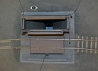
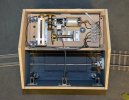
Overhead view of the tippler platform with the building removed. The left hand support for the hinged beam is cranked to clear the empty wagons. Top left is the DIN socket for electrical connection to the winding gear.


30. Tippler 003B.jpg

wagon in position on tippler platform


31. Tippler 004B.jpg

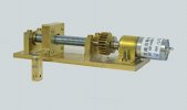
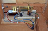
A motor/gearbox unit is connected to the winding drum by bevel gears. Two spur gears on the other side of the gearbox drive a M8 threaded rod with a captive nut which contacts a microswitch at each end cutting off power at the top and bottom of the platform's travel. The tippler is operated by a change over switch - with a full wagon in position turning the switch up raises the wagon which stops automatically at the highest point, wait a few seconds to allow the wagon to empty completely, then turn the switch down to lower the wagon which then stops automatically back at track level.


32. Tippler 005B.jpg

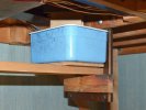
The coal is discharged into a plastic container below the baseboard, thanks to Walls ice cream. The box lid is fixed to the chute so it gives a dust tight seal when the box is clipped in place.
 

simond

Western Thunderer
This is really great, Phil, thanks for sharing.

a question if I may. Would it not have been easier to use the motion of the leadscrew to operate the tippler and the limit switches? I guess perhaps not with the leadscrew where you have it, but “in principle”?
 

PMP

Western Thunderer
From your comments I assume you’re using real coal? The reason I ask is I’ve looked at trying a similar thing for loading in 4mm but the ‘mass’ in terms of weight doesn’t give an easy flow.
Does the coal only flow when the motor is activated?
 

PhilH

Western Thunderer
This is really great, Phil, thanks for sharing.

a question if I may. Would it not have been easier to use the motion of the leadscrew to operate the tippler and the limit switches? I guess perhaps not with the leadscrew where you have it, but “in principle”?

Simon,
In principle it would have been possible to use the leadscrew to operate the tippler, but the problem is the leadscrew gives just over 1½" movement between the switches whereas the cord lifting the tippler platform requires 6" of movement. The building is just over 6" wide inside and not much more than that in length inside so I don't think fitting a leadscrew giving 6" of movement and allowing for bearings and switches, etc, at each end would be practical.

From your comments I assume you’re using real coal? The reason I ask is I’ve looked at trying a similar thing for loading in 4mm but the ‘mass’ in terms of weight doesn’t give an easy flow.
Does the coal only flow when the motor is activated?

Yes, I do use real coal and don't experience any problems using it. There's no movement of the coal until the vibrating motors are activated. Some people might worry about the dust, but I sieve the coal to remove the finest particles so there's only a small amount produced around the loading areas - natural weathering ! :)
The use of a vibrating chute at a slight angle to move the coal is just replicating the way a prototype screening plant worked, with steel plates set at a slight angle and vibrated to move the coal along, a series of holes in the plates grading the different coal sizes required.
 

PhilH

Western Thunderer
The layout needs a fair amount of coal for loading/unloading and it may be of interest to describe how it was reduced to the required size.

First with the coal inside a thick polythene bag it was crushed down with a hammer to reduce the size to about ¼". Then the coal was further reduced to the required sizes in a purpose made coal crusher - rather a 'Heath Robinson' affair, but it did the job !
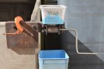
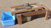
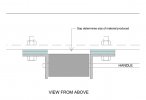
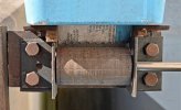
Built largely from scrap materials it comprises a length of steel angle to which are bolted two short lengths of angle which act as pivots for a steel roller which can be turned by a handle. The sketch and photo below should help to make this clear. In use the device is clamped to some firm object - in my case the wall of an old coal bunker - outside the house, the latter being important as it tends to make loads of dust.


1. Coal Crusher 001B.jpg


2. Coal Crusher Plan.jpg


3. Coal Crusher 002B.jpg

The steel roller is 1¼" diameter, a larger diameter would be better but that was the size to hand. The surface is "distressed" by longitudinal gouges round its circumference. Initially it was also provided with "teeth" in the form of short lengths of steel rod forced into holes and protruding about 1/16" from the surface. However it has been used latterly for producing coal dust to mix with the track ballast and these have been filed away. The gap between the roller and the face of the steel angle determines the size of material produced and this is adjusted by the packing pieces coloured blue in the above drawing. The material is reduced in stages, narrowing the gap each time, until the required size is reached.


4. Coal Crusher 003B.jpg

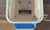
The material is fed into the device by a hopper with a flap cut into the bottom to direct the flow on to the roller.​

The coal was sized in old kitchen sieves plus the screening device shown below.


5. Coal Screen 001B.jpg


6. Coal Screen 002B.jpg

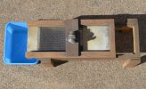
This comprises a tray with a section of aluminium mesh in the bottom mounted on a frame at a slight angle by four springs. The tray is vibrated by a small electric motor with an out of centre flywheel mounted on top.


7. Coal Samples B.jpg

Samples of coal produced - approximate nominal sizes in 7mm scale left to right: 3½", 2½" and 1½".


Focalplane

Western Thunderer
There’s coal and then there’s coal! In my experience a hard vitrinite coal is the best and that is what you appear to have, Philip. I got mine from an abandoned surface working in southern France and it took a long search to finally get some vitrinite in an outcrop deep in the workings. Most of the coal there was bituminous, dull and dusty, not worth collecting.
 

PhilH

Western Thunderer
There’s coal and then there’s coal! In my experience a hard vitrinite coal is the best and that is what you appear to have, Philip. I got mine from an abandoned surface working in southern France and it took a long search to finally get some vitrinite in an outcrop deep in the workings. Most of the coal there was bituminous, dull and dusty, not worth collecting.

I got mine in a bag from the local hardware store :)
 

PhilH

Western Thunderer
1. Boothsbank Tip.jpg

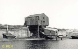
The end tippler is based on the one at Boothsbank on the NCB's Walkden Railway System, which transferred coal to barges on the Bridgewater Canal. Today the site of the tip and sidings have disappeared under a housing development and the canal basin is now a marina.

This short video shows the coal tippler in operation:


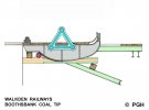
Details of the actual tippler arrangement are shown below, wagons enter from the left.


2. Tippler Drawing B.jpg

The tippler platform shown in grey is supported on each side by two triangular frames which are pivoted at their apex to a fixed bearing. The centre of gravity of the loaded wagon is slightly forward of the pivot and this, probably aided by the momentum of the wagon, causes the platform to tip thereby discharging the load. A toothed rack is provided on part of the platform frame underside, connected to a pinion (coloured red on the diagram) and by gearing to a handwheel on the platform above. This would be used to return the empty wagon to the horizontal position, aided by the counterweights fixed to the entry (left hand in diagram) end of the platform between the rails.

I haven't replicated the rack and pinion arrangement, and the required movement is carried out by a thread connected to a hidden motor and counterweights. Only the actual tip building will be provided, the canal loading chute and basin is "off scene".
 

PhilH

Western Thunderer
3. Tippler 002.jpg

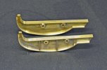
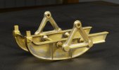
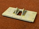
First step was to construct the tippler platform and the side frames were cut from 2mm thick brass. The top and bottom flanges and ribs were then added.


4. Tippler 003B (2).jpg

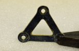
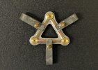
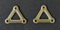
The two triangular supports for the tippler platform were constructed from 1mm thick brass.


5. Tippler 004B (2).jpg


6. Tippler 005B (2).jpg

The round corners were shaped with the aid of two pieces of steel rod turned to the required diameter.


7. Tippler 007B.jpg

Brass bushings were added front and rear for the shafts and the ribs soldered on front and rear with the aid of homemade clamps.


8. Tippler 008B.jpg

The completed supports, there are a total of 13 parts in each.


9. Tippler Frame 02B.jpg


10. Tippler Frame 03B.jpg

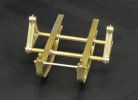
The completed tippler platform framework before painting and adding the timber deck and rails.


simond

Western Thunderer
serendipity is a wonderful thing, whilst searching the European Patent Database this morning for info relating to Michael’s brakes, I found this, which may be of inerest


Enjoy, I hope
Simon
 
Last edited:

PhilH

Western Thunderer
Thanks for the link Simon, it seems to conform exactly to the tippler at Boothsbank, and also indicates that the mechanism geared to the table incorporated a brake to control the tipping operation. Many of the collieries in the South Lancashire coalfield had coal tips on either the Bridgewater or the Leeds & Liverpool canals, sometimes reached via lengthy private lines from the collieries. The famous "Wigan Pier" has been attributed to a canal coal tip although I believe the true origins are a little different.

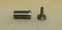
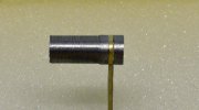
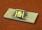
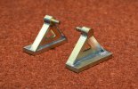
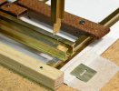
The tippler table pivots comprise vertical triangular plates supporting the bearings with flanges down each side and mounted on baseplates. The triangular plates were first soldered to the baseplates and located with 0.6mm dia. dowels to ensure they wouldn't move in subsequent soldering operations.


12. Pivot 1B.jpg

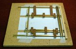
To fix the bearings in line and hence ensure free movement of the table the two sections were bolted to a piece of plywood a set distance apart and exactly opposite each other using the tapped 8BA fixing holes in the baseplates.


13. Pivot 2B.jpg

The bearings and flanges were then soldered on in single pieces spanning both verticals.


14. Pivot 3B.jpg

This gave the required result after separation of the two parts and removal of excess material.

 
Last edited:

PhilH

Western Thunderer
15. Tip Support 01B.jpg

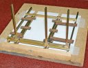
The tippler support structure was assembled as a complete unit which could be painted before installation on the layout. The brass I section beams for the tippler platform were soldered together upside down on a jig.


16. Tip Support 02B.jpg

The tops of the vertical support columns were fitted into slots on the cross beams


17. Tip Support 03B.jpg

The three columns soldered in position. The tippler itself will sit in the largest rectangular opening with its pivots supported on the double I beams.


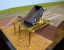
18. Tippler Support 5B.jpg

The part assembled structure in position on the layout with a wagon showing how it will operate.


19. Tippler Support 07B.jpg


20. Tippler Support 09B.jpg

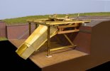
With the chute and additional supports installed under the platform. When the layout was first planned it was intended to place the tippler in a corner and little if any of the structure below and beyond the actual tippler building would have been visible, so when surveying the prototype I didn't take much notice of what was under or beyond the actual tippler building. In its current position the situation is rather different and the few rather distant views available of the prototype didn't offer much help, so the detail under the building is only a vague representation of the prototype. The steelwork is reasonably like the prototype, the timber underneath probably somewhat less so. I'm not sure what purpose some of this timber served and maybe it was part of an earlier structure. The tippler had to be rebuilt in 1914 after being demolished by a runaway train. Beyond the building is 'off scene' and the chute merely directs the tipped coal into a suitable container. It would have been nice if space had been available to include part of the canal basin with the boat loading chute and a barge to receive the coal.


21. End Tippler Support 101B.jpg

The tippler support framework painted and fixed in position. It was grit blasted and primed with U-Pol Acid #8 etch primer. At this point I wondered whether the finish coat should be light grey or light green like the colliery steelwork - and decided on the latter. The prototype was certainly a light colour when I photographed it in 1965, unfortunately in black & white.


22. End Tippler Support 102B.jpg

The chute has a removable extension to take it over the edge of the baseboard and the switch in the facia bottom right operates the tippler. The mound of coal underneath represents the inevitable spillage from the operation.


23. End Tippler Platform 03B.jpg

The timber tippler platform fixed in position after painting. The prototype had a mechanism in the rear left hand corner connected by gearing to the tippler table but without sufficient detail being available this had to be omitted. The tippler now just needs the timber building over it, which will have a removable side wall or panel on the viewing side to access the end door catch on the wagons and view the operation of the tippler.
 

PhilH

Western Thunderer
The operating mechanism for the tippler:


24. Tippler Drive 01B.jpg

This comprises a 100rpm gearhead motor connected to a M8 threaded shaft via two old Meccano gears. The shaft drives a captive nut in a brass fitting with an extended arm to which is fixed a cord connected to the tipping table. It's fitted on the layout upside down from this view.


25. Tippler Mechanism Drawing B.jpg

This diagram shows how the mechanism works. The operating cord passes through a brass tube in the retaining wall. It should really have a small pulley at the change of direction but I flared the end of the tube instead to ease its passage. The mechanism is operated by a DPDT switch and controlled by micro switches at each end of the movement. The most critical part of the movement is at the end, returning the table to line up exactly with the fixed entry/exit track and this is done independent of the mechanism by a timber beam under the table. The mechanism is therefore arranged to overwind slightly and slacken off the drive cord at that end of the travel.


26. Tippler Drive 02B.jpg

View underneath: The 12v supply enters top left, the DPDT operating switch is bottom right and the operating cord connected to the table is top right. A video of the tippler in operation is shown in Post #20
 

PhilH

Western Thunderer


28. Boothsbank Tip Sidings © PGH.jpg

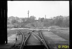
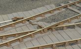
View out from the tippler building in April 1970. By that date Astley Green was the only colliery on the system still working and it closed for production later that year so its probable that the tippler saw no further use. On the left are the three full wagon sidings where wagons were left by the locomotive. The wagons were then run individually by gravity on to the tippler (immediately behind the camera) and then, after emptying, run by gravity into the two low level sidings on the right for collection by the locomotive. The point in the foreground therefore had both roads sloping but in opposite directions and instead of the conventional crossing or frog there was a hinged section of rail connected to the same lever that worked the blades.
Beyond the sidings on this side of the overbridge is the junction with the line to Astley Green which curves away to the left hidden from view. Standing on this spot today you would be viewing an estate of houses occupying the site of the sidings. Behind the camera the canal basin is now a pleasure boat marina and to the left is a pub and restaurant.


29. Tip Sidings 1B.jpg

A similar view on the layout where there was only room for single full and empty sidings.


30. Tip Sidings 2B.jpg

The moveable crossing section of rail.


31. Point Parts B.jpg

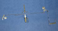
The operating parts for the point. The small crank (left) is attached to the blade tiebar by the forked link below. The large crank (right) is connected to the hinged crossing rail - shown below upside down. The operating lever (centre) has two sockets pivoted to its forked lower end to take the rods connecting it to the cranks. To complete the installation the cranks and lever were fixed in position and then the length of the rods adjusted to give the required movement after which they were soldered into the sockets. Surprisingly this all went according to plan ! The round extension below the lever pivot houses a sprung plunger which bears on the bottom of the lever and keeps it in position.


32. Tip Sidings 3B.jpg

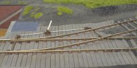
The point set for full wagons entering the tippler


33. Tip Sidings 4B.jpg

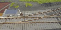
and set for empties leaving the tippler​

Locos are not required to pass over this point. The method of operation is for loaded trains of say 6 wagons to be propelled towards the tippler, the lead wagon is detached and tipped, then the loco pulls the remainder of the train clear of the point after which the empty wagon runs by gravity into the lower siding. This is repeated for the next two wagons. The loco then uncouples, collects the three empties and then pushes the remaining three full wagons individually into the tippler. So there is always at least three wagons between the loco and the tippler.
 
Top