Bob
It was a good idea until I took it out of the box, when it dawned that whilst I had originally intended to model a P&P loco, I changed my mind to make one of Polmont's allocation. I really must get around to painting it, maybe.

I've had a look at both RCTS and Yeadon and neither has a bunker view of the relevant locos, but I suspect the rear wouldn't have been much different from the front.
Re air pumps, The NB was an air railway so all passenger engines were equipped with Westinghouse equipment that included air braking on the engine. When the LNER, along with others, made the wholly retrograde step to standardise on the vacuum brake I can only conclude the additional cost of converting the loco brake to steam couldn't be justified, even though 20 odd years of compressor maintenance would surely have paid for it, As a result the locos were airbraked until withdrawal, as far as I am aware a situation that applied to all former NB engines and certainly a large quantity of GE engines, the other part of the LNER that managed to look forward.
Regards
Martin
PS Yeadon has a nearly side on view of a P&P loco which is helpful if you can borrow a copy.
PPS You need to be a bit careful with brake and heat hoses at the front as things varied over the years.

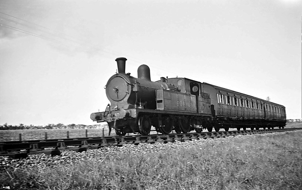 A local push and pull train at Belton on the Yarmouth Southtown-Beccles stretch of the East Suffolk Line. Victorian-built tank engine Class F1/4 2-4-2T LNER No.5731 provides the motive power. Mid-1930s-1937
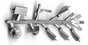

 .
. ") .
.") the heating bag's down to the left of the drawhook, hanging off the buffer beam....
the heating bag's down to the left of the drawhook, hanging off the buffer beam....