Stanier 8F in S7

DavidinAus

Western Thunderer
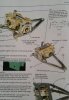
Just an update. For once, no real questions - I have ignored many people's advice anyway, I'm afraid, by dismantling the model as constructed so far, and started the painting at this early stage.

Small Chassis dismantled 1.jpg
This was partly because of the difficulty painting behind the driving wheels, and partly because I realised that I needed to put the balance weights on the wheels, and this would probably be much easier if I could lie them flat. Also I realised that the return cranks were on at an exaggerated angle, and although this makes the valve gear move more satisfyingly, I should probably re-do the soldering to make it more realistic (I think about 10 degrees is right?).

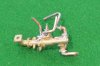
Of course to put the balance weights on is easier said than done. First of all I had to choose exactly which 8F I wanted to model! I found a picture of number (4)8067 which seems to have the right characteristics: a rivetted tender, balance wheels of the earlier type (not all of the weights are crescents) and based in the north of England. So number 8067 it will be.

Both types of weights are supplied in the MOK etches, as pairs (so four of each shape). Using the S7 Group Slaters wheels makes sandwiching the pairs of etches together relatively easy, one on each side of each wheel: the plastic spokes can be cut back a little to accommodate the etches. Not too much on the outer side, though, as the balance weights stand proud of the rims on the pictures I have seen.

Small Balance weights 2.jpg
I then filled in the gaps between the etches with Milliput filler.

Now seemed a good time to use Birchwood Casey metal black on the rods and valve gear, to obtain a good "polished steel" finish. I used Hi-Chem "All-Surface Primer" on the wheels (probably only available in Australia, but I'm sure motorcar paint shops anywhere would have a similar product) - it's a marvellous very thin and very effective metal primer: it sticks to anything, in my experience even glass or granite benchtops! Therein lies a separate story, as you might imagine ....

Finally, a "dirty black' initial topcoat. My engine is going to have a realistic (I hope) weathered appearance.

Small Balance weights 4.jpg

So there you are.

David
 

OzzyO

Western Thunderer
One thing that I would like to point out is that locos that had "plate" balance weights did not always have them all filled up to the top. The 8Fs. only had a small amount of balancing unless they were star balanced (IIRC that meant that they had50% of the reciprocating weight balanced) . That would then mean that they could then run at 60mph? With less hammer blow on the track.

If you had been making an 8F with crescent shaped balance weights and had the filled them in this would had been more correct as these were cast in to the wheels and had holes on the rear face that had plugs of lead fitted in to them.

All of this is done from what I can remember, not from any of my books so I may have some of my numbers wrong,

OzzyO.
 

Paul Kehoe

New Member
I'm looking for advice or hints as to how I could go about building an MOK kit which I've had for over a decade on my shelves.
As an aside, this seems to be a common situation amongst railway modellers: we see a kit we'd really like to build, buy it, but then don't have time to make it for years. A little while ago I told myself I had to stop buying more kits until I had built the ones I already had on the shelves! Perhaps I could even use the money I saved to do the already-purchased products better? It has taken me a couple of years to get to the stage of only having one kit left - for the Stanier 8F.
So, after building nothing longer than an 0-4-0 before, I have decided to try a 2-8-0, with near-scale dimension frames.


I sent a request for advice to the old S7 forum just after Christmas and it's only just appeared. It obviously takes a long time from Australia ..... However I now realise that this forum is where more action takes place.

After waiting a while I tried another track: I contacted Dave Sharp (who runs MOK). He has been amazingly, wonderfully, helpful. In fact he is doing some special etches to adapt his 8F kit to Scale 7 ! We (well mostly him of course) have been working on this for a little while, but don't know how well it will work as yet. Basically my request of him has been to set the outside frame width at 29mm (I think 30mm is the perfectly correct width, but Dave and I concluded that it was not realistic to try to construct the model using that dimension). The layout of the custom etch that he has suggested would re-make the central frame stretchers (if that's what all the parts which go between the two vertical frames are called), the motion brackets and the cylinder parts.

At the moment we don't know if this is going to work, especially with an eight-coupled locomotive. However my reasoning was a little like this: I gather the MOK Ivatt S7 kit uses 29mm frames, and the 8 wheels rather than six will actually need less sideways movement on the inner axles, as the two inner axles are not at the mid point between the outer axles.

I intend to make it with Slaters wheels, and get them altered to S7 profile; I don't know how I could obtain anything else, anyway. I'm probably going to use split-axles if I can learn how to do this (can anyone point me to a good article on how to do this with Slaters wheels?). However I could try the "American" method of loco and tender pickups on opposite sides, or even go for radio control. The last of these is attractive, but I know nothing of it as yet, and am going into (for me) the unknown anyway, as this is my first non-tank engine as well as first with more than 4 coupled wheels! Which way to go?

I had been thinking of an RG7 motor, but having seen some posts on WT, perhaps I should go for an ABC Mini-7 gearbox and a different motor. What do WT readers recommend? - I've saved money not buying that Lankykits bogie box van, those nice JustLikeTheRealThing wagons, that LNWR G2 kit I liked the look of, etc.

If it works, I hope this will be another kit that Scale Seven Group members will buy, for Dave Sharp's sake: support from him and others like him is what S7 needs, in my opinion.

Any advice gratefully received.

David C
Hi David, I am in Melbourne and understand the problems dealing with overseas suppliers, some, like the chap who now owns MOK obviously, from what you say, brillinat, others best forgotten! With repect to your queries, which I am probably incorrectly interpreting, why do Slaters wheels need to have split axles? Plastic centres ensure isolation. ABC Gears combinations are, in my opinion, the best way to go for motive power and they are most helpful with advice and suggestions. Pick-up from the rails? Neanderthal! I switched to radio control via the Red Arrow radio system (not the infra red) and it works superbly. But you must get the mechanical engineering of the chassis spot on....and isn't that how it should be? No more worries about pick-up, isolation, dirty track, rust et al. I have no connection with Red Arrow other than knowing that Steve Leyland is a TOP BLOKE....Oz for jolly good chap!!!
 

DavidinAus

Western Thunderer
Brake gear.

One day, perhaps, perhaps, I will take the wheels off, unstick the Araldite and Milliput with boiling water, and take the filling out from between the balance weights and reassemble the whole lot. Until then I will just see it as dirt stuck between the plates, and leave it as it is!

Meanwhile, on to the brake gear.
A problem with all systems where power is picked up from the rails is that brake shoes realistically close to the wheel treads need to be isolated from those on the other side and from the frames, or else short circuits will occur. DC or DCC, I think. Now my system is going to have no pickups from the driving wheels, but the brakeshoes as made in the kit will short-circuit from one side to the other. What options do I have?

My first thought was to make new brake hangers by acrylic/epoxy molding. So I bought a Sylmasta kit and made molds for the brake hangers for the locomotive and tender.Small Mould for Brake hangers.jpg

I then made castings first in polyester:
Small Brake hanger polyester moldings.jpg

These were too friable and brittle, however, so by default I tried molding in Araldite, which was more robust, but full of bubbles:
Small Brake hanger epoxy moldings.jpg

Even these looked unlikely to survive very long in general use, though. Contacting friends for advice off-line suggested that I was trying to make castings of too much: it would be better to make castings of just the brake shoes.
However to do that meant filing all the brake shoes off the hangers (fourteen!) and both making and fitting accurate copies of the shoes onto each hanger. Then it occurred to me - I don't need to take all the brake shoe off, just the surface which will be in contact with the wheel tread.
So I found some 2mm wide Plastikard strip, and have carefully filed sufficient off the surface of the brake shoes to glue a strip of Plastikard onto each shoe.
Small Brake hangers.jpg

So the one on the left has been filed back, and the ones on the right show the Plastikard in place.

Once I came to try to fit them to the frames the next adjustment became necessary. As the frames are set at nearly the correct prototype width, they are much closer behind the wheels than in Finescale. If the brake hangers are fitted as made, the hangers are too far away from the frames, the shoes are outside the wheel rims and the outside parts of the shoes contact the coupling rods and stop them rotating. So now I became more grateful that the main parts of the brake hangers are metal, not epoxy! The two on the left of the picture above have had the posts from which the hangers are suspended shortened, whilst the right hand one is the original length. I think that this adjustment would have been near-impossible using plastic parts.

Now I just have to fit them, one or two at a time, and make sure the wheels still go round after each fitting.

David
 

DavidinAus

Western Thunderer
I have reached the stage of being able to run the chassis up and down my test track even with the locomotive brake gear in place, and it still moves, as you will see (I hope, as I try putting my first YouTube video onto WT!).


This is the model as it is now, though, with the pony truck in place (unlike the videos).

Small Stanier 8F body Nov 2015.jpg

That is the reason for this post: can anyone suggest what is the best way to add downward pressure on the pony truck wheels? I have put lead into the box which makes the body of the pony truck, and it still rides up over the curves of my test track. It is more an issue because of the S7 wheels, I'm sure. Clearly I need to add some downward springing to the truck, but what is the best way to do so?
This video shows it running without the pony truck, which can be seen on the baseboard after I took it off the chassis!


I have ordered some phosphor-bronze wire and some phosphor-bronze strip from Eilleen's Emporium, and some piano wire, so that I can do trials of various methods. However it then occurred to me that I should ask for advice before doing anything further - someone must have faced this difficulty before.

Also, as I am asking for help .... as I come to the detailed parts of the MOK body, the instructions run out! I have quite a lot of parts still to go. The lost-wax brass castings are all reasonably straightforward, but some of the tiny etched parts are hard to identify. If I spend enough time looking at pictures I have no doubt that I will eventually work out where to put all the parts shown in this picture.

Small parts for 8F body.jpg


However once again someone who has built this kit, or knows the prototype well, may be able to tell me where to put this parts:

No. 110 - the two rivetted discs in the centre (still on a connecting part of the etch).
No. 134, a larger disc
No. 143 (x3): little teardrop shaped parts
No. 155 (x2)
I know no.s 158 and 159 are the deflector irons.
No. 182 (x2)
No. 304 (x4)
No.s 382, 383 and 384 (or are they from the tender?)

All help, as ever, gratefully received.

David
 
Last edited:

Dikitriki

Flying Squad
Hi David,

From memory:
110 - bearing covers for the tender brake cross shaft - fits to outside of frames.
155 - pipe flanges, not sure where from.
302 - lamp irons - throw away and use cast brass ones instead.
382 - 384 - AWS protection plate and detail - fits to bottom of front buffer beam IFF your loco is AWS fitted.

The others may of course be spares/not used. Tony might be along to say something more.

Richard
 

Scale7JB

Western Thunderer
Are the wheels sprung in the pony truck? If so you can use a bearing plate which rubs against the top of the pony truck frames..

I've done the same on my 2 k2's and it works perfectly..

JB.
 

DavidinAus

Western Thunderer
I hadn't planned to spring the pony truck and would have to dismantle it if I need to do that. I'd hoped to get away with something simpler. Two
phosphor-bronze strips or wires pressing down on each side?

Thanks for the info. Richard. From whom do I buy the cast brass lamp irons?
I think the 155 pipe flanges may be for the ejector pipe?

David
 

Scale7JB

Western Thunderer
Yes, thinking about it, springing between the main frames and the pony track frames would do it too.

Depending on the weight of the loco itself you could probably afford to be quite heave with the springs.

JB.
 

DavidinAus

Western Thunderer
Further to my post above, I'm still unsure about how to spring the pony truck. I'll attach a few pictures to illustrate the situation, and will once again be grateful for hints/advice/thoughts.

Number 1 show the pony truck in position from the side. Small Pony truck springing 01.jpg
No.2 shows it from the front.
Small Pony truck springing 02.jpg For no.3 I have lifted the body up with some scrap metal
Small Pony truck springing 03.jpg No.4 shows the situation from underneath
Small Pony truck springing 04.jpg No.5 shows the pony truck detached.
Small Pony truck springing 05.jpg

The issue is that I need to add some sprung downward force on the pony truck, and I am unsure of the best way to do it whilst allowing sideways movement that is necessary. I have added lead weight within the body of the pony truck but even with that is comes off on curves too easily. In pictures 4 and 5 there is a curved flat plate above the pony truck just above the circular etched parts of the upper surface of the pony truck, as if little coil springs could be added here.
I have bought some phosphor-bronze wire which I could try to bend into coil springs, but then would that allow sufficient sideways movement?
As another option, I have thought of bending wire like this:


upload_2015-11-22_15-35-52.png

and fixing across the top of the pony truck with the curved parts at the top bearing on the curved plate provided, to give springing, which I hope would be on each side relatively independent of the other.

I ordered supplies of raw materials that might be useful (0.15 and 0.3mm phosphor-bronze strip, and 0.5m p-b wire, plus 0.36, 0.7 and 1,0mm piano wire). The loco. body is quite heavy (420g as built so far), so quite heavy springing might be possible, but I have no idea how much is needed.

So once again, does anyone have any advice to give before I start out on this?

David
 
Last edited:

markjj

Western Thunderer
2015-11-22 09.40.39.jpg Hello David,
On the Standard 4mt kit it used to come with a sprung plunger that pushes down on the bogie with a hook arrangement that follows the arc of the bogie swing. I think on later kits this plunger has gone though possibly to save money but the 4mt kit uses a very heavy brass cast bogie so it may not be necessary. I copied the pictures from the instructions the kits are not that far advanced yet..... 2015-11-22 09.32.16.jpg2015-11-22 09.30.45.jpg
 

Attachments

  • 2015-11-22 09.40.39.jpg
    2015-11-22 09.40.39.jpg
    102.9 KB · Views: 26
Last edited:

number6

Member
I admire from afar the proper engineering solutions to problems like this - having had plenty like it in 4mm. - so I'll just chuck this solution out there should all else fail.

I use a small block of dense foam - cut in height and width using trial and error this then sits above your pony truck either attached to the truck itself and sliding against the body or around the other way if there is more free surface.

This allows movement in all planes but applies a nice constant pressure. You may worry about appearance but I find it has extra purpose in filling larger than scale gaps and becomes nearly invisible once the engine is sat on the track.

It has an additional 'mechanical' advantage as it can also guide the body of the engine into curves in a more prototypical manner than a 'flapping' pony truck can. I find it particularly useful on 2.6.0s where the mass of the loco far exceeds the tracking of the pony truck. 4.4.0s and 4.4.2s also respond well, compensating for the short coupled wheelbase.

I know this would seem an anathema to many but should all else fail: try it! I use dense black foam of the kind that comes in some electronic item packaging: Heljan diesels are also packed in it.

Regards
Raphael
 

DavidinAus

Western Thunderer
Ah! It's been a while. Other things like work have been distracting me from the really important parts of life ....
Anyway I returned to my 8F recently. I have solved the issue of the pony truck by adding a strip of thin nickel silver to apply downward pressure on the pony truck, and this seems to keep it on the track (on my reverse-curved test track, admittedly no pointwork testing as yet).

Now onto some of the details on the locomotive. The Stanier 8F has an “Exhaust Steam Injector” on the right under the cab, and a “Live Steam Injector” on the left. The MOK kit has lost-wax castings of both, but the instructions are sketchy about how and exactly where to put them. When I looked at the engineers drawings in the "Locomotive Profiles" books, it became obvious that the live steam injector molding was incorrect. There should be four pipes coming off it or going to it. Water supply above the outgoing water to the boiler, on the inside surface, Live steam supply at the front, and overflow at the back. The MOK molding had four places for pipes, but two were on the side and two on the rear. In looking on the ‘net I had found illustrations of the injectors, and information that Laurie Griffin manufactures very good castings of both exhaust and live steam injectors, so I bought some by mail order. It's alright for you guys in England, they took a long time to get to me: I think they took airmail to Sydney airport, and Hairy-nosed Wombat mail over the 70km from there!

Small Live Steam Injector Moldings.jpeg
MOK live steam injector casting on left, Laurie Griffin on right.

When they arrived they were clearly an improvement on the MOK ones in terms of detail, but the Laurie Griffin live steam injector was apparently wrong also! The L-G live steam injector only had three pipe fittings. I can only assume that there were lots of different types of live steam injectors, and both MOK and LG are correct, for different models of injector. In the end, the L-G one looked better, so I have used that one, fitting the overflow pipe to the bottom of the injector casting.

Small Frames with old injector.jpeg [click to enlarge]
When I had put the exhaust steam injector onto the frames it involved fitting the exhaust steam pipe running from the cylinders down to the injector. It is difficult to form the reverse bend at the rear of the locomotive, and I hadn’t bent it quite correctly, leaving the pipe running at an angle down the frames. The Laurie Griffin exhaust injector molding includes last bend of this pipe, so it gave me an opportunity to correct this error.

However the L-G injector comes in five pieces, which need to be soldered together, and then the four pipes have to be soldered onto the injector, without any of the other joints becoming un-soldered! I have had to guess how long the pipes need to be, but cut them over-length and then shortened them progressively It took me all day, but here are the final results:

Small Both injectors with pipes.jpg Small Both injectors with pipes 2.jpeg

Clearly they have yet to go in place, but I might paint them first – it will be difficult after they are fitted. The Laurie Griffin exhaust steam injector (on the left in both pictures above) has exquisite detail, so I don’t want to mess it up with a poor paint job.

There's a guy called David Smith, whose page I found on the 'net whilst searching for pictures of injectors, who has put super detail on a Finescale RTR 8F and his made-from-scratch injector(s) look amazing, but I've no idea how it's done, and that is clearly light-years away from what I could acheive! [pity about the look of the wheels on his otherwise awe-inspiring models]

David
 

Attachments

  • Small New Exhaust Stem Injector.jpeg
    Small New Exhaust Stem Injector.jpeg
    162.7 KB · Views: 28

adrian

Flying Squad
There's a guy called David Smith, whose page I found on the 'net whilst searching for pictures of injectors, who has put super detail on a Finescale RTR 8F and his made-from-scratch injector(s) look amazing, but I've no idea how it's done,
David is a member on WT, @Isambarduk . They do look good but it is possible to see how they could be made up, a selection of bar stock turned up with a few rectangular and square sections. It looks like a few bits are pinned in place then a fillet of solder to make it look like a casting.

The other alternatives are from Hobbyhorse but I haven't got the references to hand at the moment so I can't tell if they are any better/different.
LMS – London Midland Scottish Railway
 

DavidinAus

Western Thunderer
I have looked at Hobbyhorse, and their live steam injector looks the same overall pattern as the MOK one.
7I035
However the drawings (and photographs, although less obviously) in the Locomotive Profiles book clearly show pipes coming out of the injector on three sides (it is fixed to the steps on the outside edge, I think). Otherwise I'd be declaring that Laurie Griffin must be incorrect and the MOK correct, even if less finely detailed!
 

Isambarduk

Western Thunderer
"There's a guy called David Smith,"

Indeed, there is; that would be me :) And I am enjoying your thread, BTW.

"whose page I found on the 'net whilst searching for pictures of injectors, who has put super detail on a Finescale RTR 8F and his made-from-scratch injector(s) look amazing, but I've no idea how it's done, and that is clearly light-years away from what I could achieve!"

Thank you for your kind words, David, but it's only a matter of practice, patience and having some machine tools. As to how it's done (the injector appears about halfway down the page where I wrote up the reworking of the FineScaleBrass 8F: www.davidlosmith.co.uk/LMS_8F.htm), if you twiddle the handles on the lathe and milling machine by the right amounts and in the right order you finish up with a kit of parts to press and solder together - there's really no more to it, honest.

LMS-Injectors.jpg
Injectors from scratch on a FineScaleBrass Black Five (left) and Jubilee (right) with a few spares for later builds in front
See: www.davidlosmith.co.uk/LMS_Black_Five_Jubilee.htm

"[pity about the look of the wheels on his otherwise awe-inspiring models]"

Fair enough but I am more of a model engineer than a railway modeller so the wheels do not offend me. Reworking these RTR models is all very well but you do have to stop somewhere and accept the compromises that come with the commercial design. I think I have learnt now that I gain far more satisfaction and enjoyment from building from scratch or using the parts of a decent kit as a basis for a scratch-build. That said, I recently embarked on reworking a loco from the same stable, a GWR Class 1361 0-6-0ST, which I have recently started to write-up here: www.westernthunder.co.uk/index.php?threads/reworking-a-san-cheng-tower-gwr-1361-0-6-0st.5221/ so perhaps I haven't learnt the lesson just yet.

David

David L O Smith
 
Last edited:
Top