TFW’s workshop

Rubbish!
  • Tim Watson

    Western Thunderer
    Afraid I stopped short of carving in the frogs in the bricks, more dereliction of duty.
    nwlw20.jpg


    With lath & plaster ceilings added
    htgxtu.jpg

    Tim
     
    Last edited:
    Any demolition site would have a bonfire
  • Tim Watson

    Western Thunderer
    An architect friend of mine, John Burkett-Smith, suggested “that a bonfire on site would be almost inevitable, to burn laths and rotten and small timber. Just a volcano of unburnt bits and a crater of ashes in the centre. If it was against a wall, any bricks would be scorched reddish by the heat.”
    So that’s what I did
    mrcxae.jpg

    33tqo82.jpg


    Adds a bit of colour.

    Tim
     
    Dereliction in context
  • Tim Watson

    Western Thunderer
    The little dereliction scene can now be seen in context close to the wall on top of Gasworks Tunnel. Notice the cat on the hot tin roof.
    149ccno.jpg


    2a8jbia.jpg


    It’s interesting to compare the original site:
    35a8zk9.jpg


    With how it is now:
    ny5gkx.jpg

    Bill Stickers has been around and the Mission building has now been weathered into the style of the layout, but will need more backyard stuff.

    Tim
     
    Last edited:
    Wear & tear
  • Tim Watson

    Western Thunderer
    Prior to CF going to the Basingstoke show a few weeks ago, the Stirling 8’ single No 547 had a bit of work done on it to tighten up on clearances. As is well known, the Stirling singles don’t have any clearances, so any wear can have lively results, electrically. The drive wheel gear box had become a little loose in the frames and so some judicious packing and re-setting have solved that problem, whilst at the same time I re-trimmed the engine for ride height. Indeed, the two singles, No 21 the Ivatt 7’ rebuild, and No 547 performed near faultlessly for the duration of the show.


    Unfortunately, the H1 class Baldwin 2-6-0 failed to proceed, whilst hauling 30 wagons at Basingstoke on the Saturday afternoon. A preliminary strip down at the show pointed at wear in the gear box. On examination at home, it became obvious that the worm wheel had worn out, with the worm also showing signs of some wear.

    ipmhjk.jpg

    1zpjtcz.jpg


    About ten years ago, the 1.5mm steel cross shaft that the worm wheel ran on had enlarged its bearing hole in the gear box sides, which were reamed out and the shaft replaced by a new 1.8mm diameter pivot steel shaft. The worm and small reduction gear were also replaced at the same time, even though they were not greatly worn. On rummaging through the spare gears pots they were found again and the worm gear rebored to fit the larger shaft. With it all back together again it ran smoothly and should be good for a few more miles.

    1zpjtcz.jpg


    This engine has probably done 300 miles since it’s introduction in 1996. One of the problems with old locos is remembering how they were made and assembled, there are 32 x 16 & 14 BA screws holding the Baldwin together: recent engines are far simpler.

    Both engines will now go through the paint shops for a tidy up.


    Tim
     
    Busy at Kings Cross
  • Tim Watson

    Western Thunderer
    We have CF fully erected at Keen House at the moment. To save effort when setting up at a show, the back scenes have been fettled so that they drop into place relatively easily and are held in place by catches and flush mounts. The joints have been sharpened up to be less obvious and a storm has developed over KX Goods Yard. The reason for this is that the lighting proscenium can cast a diagonal shadow on the sky, so it will help to disguise the problem. The other end was a little more tricky to access...


    The back of York Way has also had some detail added so it will be ready for Five Arch signal box, which is currently being made in Belgium. There is a lot more ‘finishing’ & tidying to do in this area, although it is not readily visible from the front.


    The most important innovation, that will revolutionise operation, has been to arrange imaging through the back scene of the Goods Yard throat, Mrs W’s yard ramp and the mainlines behind.

    All achieved by using an iPad Pro, set up as seen. This fits onto a ledge fixed to the GY board and there is a small hole in the sky through which to capture the image. The screen is easily visible from a wide range of angles. If you look carefully at the picture of the backscene you can just see the hole.

    Really good to have the layout up in the Club to work on in this way, it is relatively uncommon.

    Tim
     
    The Midland Roundhouse
  • Tim Watson

    Western Thunderer
    A prominent landmark in Kings Cross GY was the roundhouse, originally made for the Midland Railway. This was demolished in 1931, but it has always been in the plan to include it on the layout.
    24o0ih3.jpg


    It would sit behind the ‘elbow’ on York Way where there is quite an awkward patch of ground.
    ih6x5h.jpg


    There was never going to be enough room to model it ‘in the round’ and simply painting it onto the back scene would have been challenging. So I made a rough placeholder out of card, approximately painted to see if a silhouette structure would work.
    vr9a4g.jpg


    The effect was quite encouraging, but the colour saturation was too strong and the perspective would need to be worked out very carefully. A new card silhouette was made that was designed to be both semi-curved, but also painted to represent the cylinders, cones and frusta of this complicated building. Once painted it was fixed to a plywood former, giving a rather alarming shape when viewed from the wrong aspect.
    x2w1f9.jpg


    The painting is a bit impressionist in style but the shadowing is correct for our lighting. The ground will need to be made up around the sides of the building where the painted perspective kicks in.
    t9tstd.jpg


    When viewed side on, the effect is quite distressing.
    1z15h0m.jpg


    From normal viewing distances the round house merges quite nicely into the haze. There will probably now be scope for representing Top Shed between the roundhouse and the saw tooth roofs of the St Pancras Goods Station, next to the NLR incline.
    2pz0em9.jpg


    Quite a fun days work.

    Tim
     
    Rather stormy of late.
  • Tim Watson

    Western Thunderer
    Inspired by our rather busy and spectacular weather systems of late, I have extended the storm on CF.

    7C3ABB18-61D9-4F9A-8D51-C3573823229D.jpeg.075d33cb2937c53db413e476ba378f79.jpeg


    It also serves to ‘lose’ the hole in the sky.

    The layout has now been put into hibernation until September, so here is an exciting picture of the storage boxes.

    4DFA8F40-F63F-4219-B02D-A36819AC13F5.jpeg.54b48e5e1374e17db706eec2b3ec80d9.jpeg


    With all the work that has been undertaken of late I would expect we will have trimmed off 10-15 min for set up and take down times: not at all trivial when exhibiting a layout of this size and complexity.

    Tim
     
    Back to the 9P
  • Tim Watson

    Western Thunderer
    I have resumed work on Valour, the GC 9P / LNER B3 over the last couple of days. I have etches for the engine & self trimming tender reduced from 4mm scale, courtesy of Nick Easton & Paul Craig (if anyone is interested in a set - as a scratch building aid - please PM me). Even though the chassis could be used with extra bearings and spacers I preferred to make up a conventional phosphor bronze and double sided PCB structure. I know these work well on CF. The errant extra holes in the PB strip are a function of using some frame material from a previous project.

    2h6ubzl.jpg

    The two brass tubes and 14BA bolts that are used to set up the chassis are old faithfuls: they have been used on all my scratch built engines since 1982 and are removed once the chassis is soldered up. The alignment of the frames is simply checked by using drills as sighting rods and then the double sided PCB soldered into place.


    t7moeb.jpg

    The kit frames are in 8 thou nickel silver and are used as an overlay and will also support the cylinders etc, supplied in the kit. However, I wanted to have the front end removable so that the cylinders & motion support brackets can be made away from the rest of the engine.


    2hz0ccx.jpg

    The front assembly locks into place and is held precisely by two 16BA & one 14BA bolt. The kit is supplied with the spring etches and so it would have been churlish not to fit them - they can be seen quite well through the large wheels.


    s29lhf.jpg


    2d1l4t2.jpg

    The rear cosmetic frames are fixed to the main sub assembly with 16BA bolts and the axle holes opened up to 1.6mm, so as not to impinge on the 2mm Association brass stub axles. The wheels are only placed loosely in the chassis, at the moment. I will set the chassis up with some trial muffs shortly and, of course, make the coupling rods. The worm gear head will be a massive lump of brass that will also occupy the ash pan.

    Quite quick progress, for me, but it does help having the etches. Valour should look very fine in full GC livery on CF.


    Tim
     
    Last edited:
    Fiddly bits...
  • Tim Watson

    Western Thunderer
    The reason for making Valour’s front end removable was to enable the front end to be made independent from the main chassis as it is quite complicated, with an awkward motion support bracket. As the etch has been made in 8 thou nickel silver, the slots or tabs need adjustment; I find a fine slotting file ideal for opening out any slots. Careful cleaning up of the etch cusp is also important to ensure a good fit of components, when dealing with a kit that has been reduced from four to two mm scale.

    The slide bars consist of two components that make up a Tee section.
    2jrtjc.jpg


    The motion support bracket folds up into the required shape very well and it simply requires the slidebars soldering in place.
    iqwiec.jpg


    Four hours later...
    m920kp.jpg

    When people look at models they often say, “You must have a lot of patience”. I think it’s actually more a case of perseverance.

    The outside cylinders are angled and so need to be lined up carefully with the centre driving wheel. This was achieved with sighting rods which were also used to align the motion support bracket with the cylinders.
    icl2eo.jpg


    The L&R brackets are held in place with the two 16 BA bolts at the front with some PCB on top to stabilise them. These brackets could be permanently soldered to the front frames when the detailing and mechanical bits are complete, if the PCB is too visible under the boiler.
    14nkc92.jpg


    The next job will be to machine the rear cylinder covers and stuffing boxes, the piston guides to fit in the motion support brackets, followed by the crossheads and piston rods.

    The final picture is for scale:
    qzj2tx.jpg


    Tim
     
    Annoying noise
  • Tim Watson

    Western Thunderer
    I wasn’t happy that Valour was noisier than it should be, but at certain speeds it would quieten down. I traced the noise down to the fact that the motor has quite a bit of end play on the shaft and the back of the flywheel was slapping the bearing face at certain speeds. The flywheel was removed (by putting the soldering iron on it at 450 deg C to kill the Loctite) and was then advanced down the shaft by less than 0.5mm. She now runs with just the rumble of the gears and also free-wheels better. Noise = inefficiency.


    Tim
     
    I hate steps
  • Tim Watson

    Western Thunderer
    Am I the only one that dislikes making tender & engine steps? I have made them up from the etches, but the tender ones were a bit tricky because there is a curve / angled area above the top step.


    The etched top of the step was bent over and burnished to give a sharp bracket to solder to the tender body.

    The tricky bit was that the change in angle occurs below that. There seems to be variations in the tenders as to how pronounced this is, but in the self trimming tender it seems quite subtle. Packing the top of the step above the vice and then bending over with a file, to exert an even pressure, produced a regular shape for all four steps.


    Soldering on the step bodies was straightforward. The steps themselves were etched in the kit, but at 8 thou thick are over-scale and jolly fiddly to handle. I therefore made new steps from 5 thou N/S strip. The end was bent up at 90 degrees to solder to the backing plate and then the rough size of the step weakened in the strip with a pair of side cutters.


    The long strip was then much easier to hold in place whilst the soldering iron was bought in to flash the tinned joint. After placement the fatigued/weakened area allows the holding piece to be snapped off the step.


    On the engine cab steps, the design is slightly different with a groove or slot to hold the steps and so the individual steps were soldered into place directly, being held by some titanium tweezers that will not take up soft solder.


    The half etched back plate for the steps produced a rather weak structure and so a bracing bracket was sweated in behind, which is also prototypical.


    All OK in the end, but not my favourite job on an engine.


    Tim
     
    Tries hard, could do better.
  • Tim Watson

    Western Thunderer
    I couldn’t quite see what was wrong with the steps but they didn’t sit right. Tony Gee fortunately put me wise to the problem. The middle step should be upside down, with the support bracket underneath, not above. That way it sits in next to the angled piece rather better. Thirty minutes work to make and fit some new steps (I’ve got my eye in on this step making lark).


    The steps are a little short of the buffer beam at the back because there is no side upstand.


    Tim
     
    Back to Valour
  • Tim Watson

    Western Thunderer
    Valour now has two safety valves. The low shroud was made by soldering a piece of brass the correct thickness to a larger lump so that it could be held. The two holes were then drilled, the top milled out and the sides were filed to give the base effect.

    The shroud was then removed from the big block and two safety valves turned from a non-tarnishing metal.


    There is a nice casting available from N Brass, but it is a little bit big and doesn’t quite get the effect of the valves sitting inside the shroud.

    ..and the brass might tarnish...


    Tim
     
    Tube modelling 35 years on.
  • Tim Watson

    Western Thunderer
    I recently retrieved the cardboard placeholder model of York Road tube station from Keen House, prior to going on holiday in Cornwall.

    This has enabled me to make a good start on the definitive building: which is approximately 35 years since I made the original Cally station. I always like to use a substantial core for my buildings, in this case producing something like a modern concrete building structure.

    In comparison with its completely hand made predecessor, the new tube station is using the latest in technologies for its construction, with 3D printed window and dental course mouldings courtesy of Richard Wilson with equally superb etched windows and fittings, courtesy of Jim Watt.

    The front walls are cut straightforwardly from styrene sheet, but there will still be quite a few subtle layers and motifs to add.


    The interior will be tricky to model,
    as the righthand end is severely truncated in depth. It could actually be modelled with the shutters down - in closed condition (1932 onwards) - but that would be a bit of a shame.

    We are returning from Cornwall very shortly, but progress on the building should continue. It might, however, be interrupted by this little chap, who we will be getting in mid August.


    Tim
     
    Butchery
  • Tim Watson

    Western Thunderer
    Life has become a bit brutal on CF just lately.
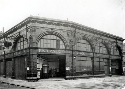
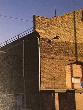
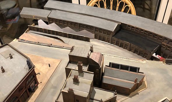
    The representation of the KX Goods Yard has featured some magnificent (and large) warehouses, based on some of the buildings at KX, that Mike Randall laser cut and made to produce a critical structural mass. In fact, the warehouse had already been shortened at the front by a bay, before our MRJ photoshoot last February.

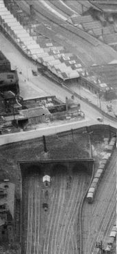
    The problem is that these big buildings aren’t quite right for this part of the yard, as they should have a whole load of canopies and smaller structures at 90 degrees to them - the famous potato market.

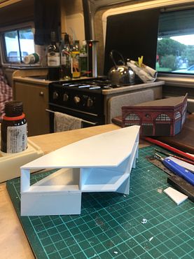
    We never claim 100% accuracy with CF, especially when we have to compromise on space grounds. So over the last few weeks I kept thinking it was time to do something about this. The warehouse was taken outside and a jig saw applied, lopping off the first floor on the nearer building over a few bays.

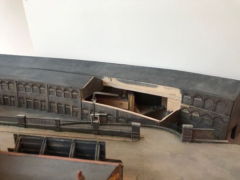
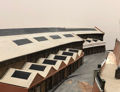
    The front wall was reinstated as the wall at the back and a flat area filled in, ready to take four hipped roofs with a parapet in front.

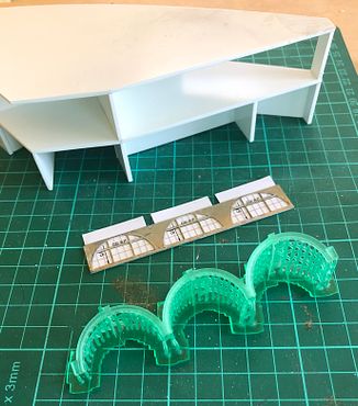
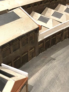
    Canopies and the beginnings of the massed smaller roofs were still lacking. I therefore took a finer saw and Stanley knife to the ground floor area at the south (left hand) end of the building, with a view to moving it forwards to make the offices and ‘inside’ warehouses.

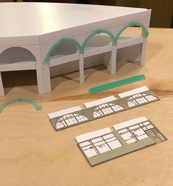
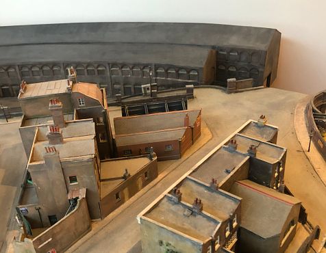
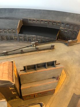
    Various styles of roof were sketched out with paper templates but six pitched roofs should look about right; the shorter, long building will also get taken to the layout boundary (the overhanging bit visible in the picture was the sacrificed roof from the north end)

    What can also be seen in this picture is that the south-facing ramp road has been removed. At the time we started sketching out this area we knew that there was an access road to the yard, but with the big warehouses hard up against York Way viaduct there wasn’t space to put it in correctly - so we turned it the other way round. With the modifications to the warehouses, it became apparent that there would be space for a correctly orientated ramp. The pavement and railing wall were lifted and the ramp and retaining walls splintered off; fairly traumatically as it happens.

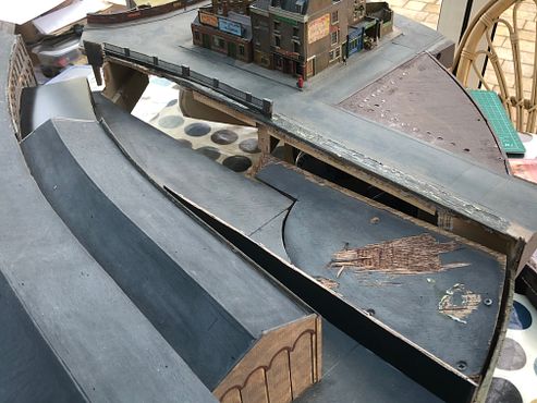
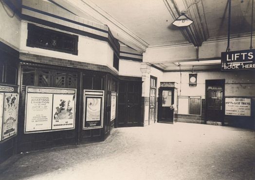
    The structural integrity of the board was beginning to become compromised at this point, so some remedial blocking and gluing was needed to reinforce the node where quite a lot of stresses accumulate (the tube station is removed in these images).

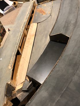
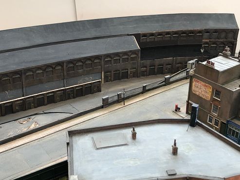
    The current status has all the reinforcements and the footings in place for the new retaining wall. The new ramp road will be modelled at the far south end, with the gates closed: It was originally an access route for some cattle pens, although these were long gone by our time period. The solid potato warehouses will be supplemented by open awnings which will butt hard up to the retaking wall and the railed fence will be moved south. The north end will feature a wall which should be good for some advertising hoardings and a bit of colour. This little patch should all end up being that bit more convincing.

    Whilst this whole area will look quite different when complete, is this butchery fine scale modelling? I hope that not too many illusions about how we plan CF to the ‘Nth’ degree have been shattered - we never have - it just evolves...

    Happy New Year to all and looking forward to ‘21!
    Tim
     
    Last edited:
    On your knees
  • Tim Watson

    Western Thunderer
    It is fascinating how adding one architectural feature suddenly ‘places’ the goods sheds as being based on KX. That feature is a ‘knee’ on each corner of the main, long, sheds.

    This part image is from ‘An Exceedingly Commodious Goods Station’ an archaeological survey by Haslam & Thompson. A very useful book, if you are making a model of Kings Cross Goods Depot.
    On the model

    And in the overall scene

    I am very pleased with the effect these have. I wasn’t convinced that the atmosphere of the sheds was quite right for KX, it’s probably getting better now.

    Tim
     
    Something a bit different
  • Tim Watson

    Western Thunderer
    Interesting how things develop. On another part of the forum I noticed that Mike Trice had made a 3D print of the LNER Coronation beaver-tail observation car. I cheekily asked if it could be produced in 2mm scale. A little while later this package arrived.

    Mike has made a superb job of the design and although some parts of the components are quite fragile I think it ‘is a goer’ as a basis for a 2mm model. The window vents are very delicate, but will sustain support from the glazing. The finish is outstanding. An added bonus is the interior.

    What is so topical is that the prototype, no. 1729, has just been unveiled after a lengthy restoration and features in an excellent article in the current issue of Steam Railway.

    There is now the minor issue of how to re-create the stainless steel trim on the beaver tail, but I have some ideas for that. The rest of the train will also now be needed: at least we have the Lonestar A4 to go on the front end!

    Tim
     
    Top